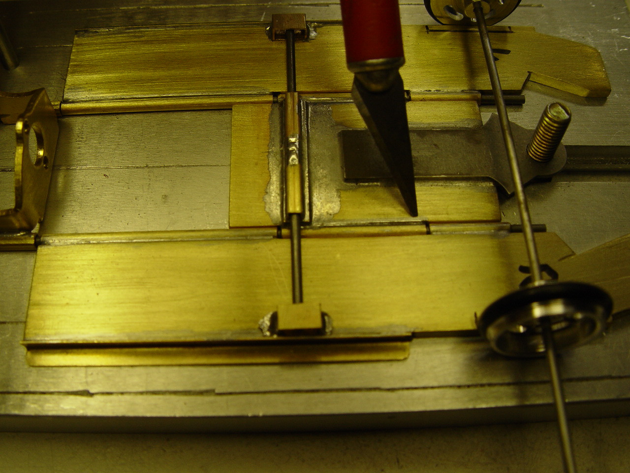
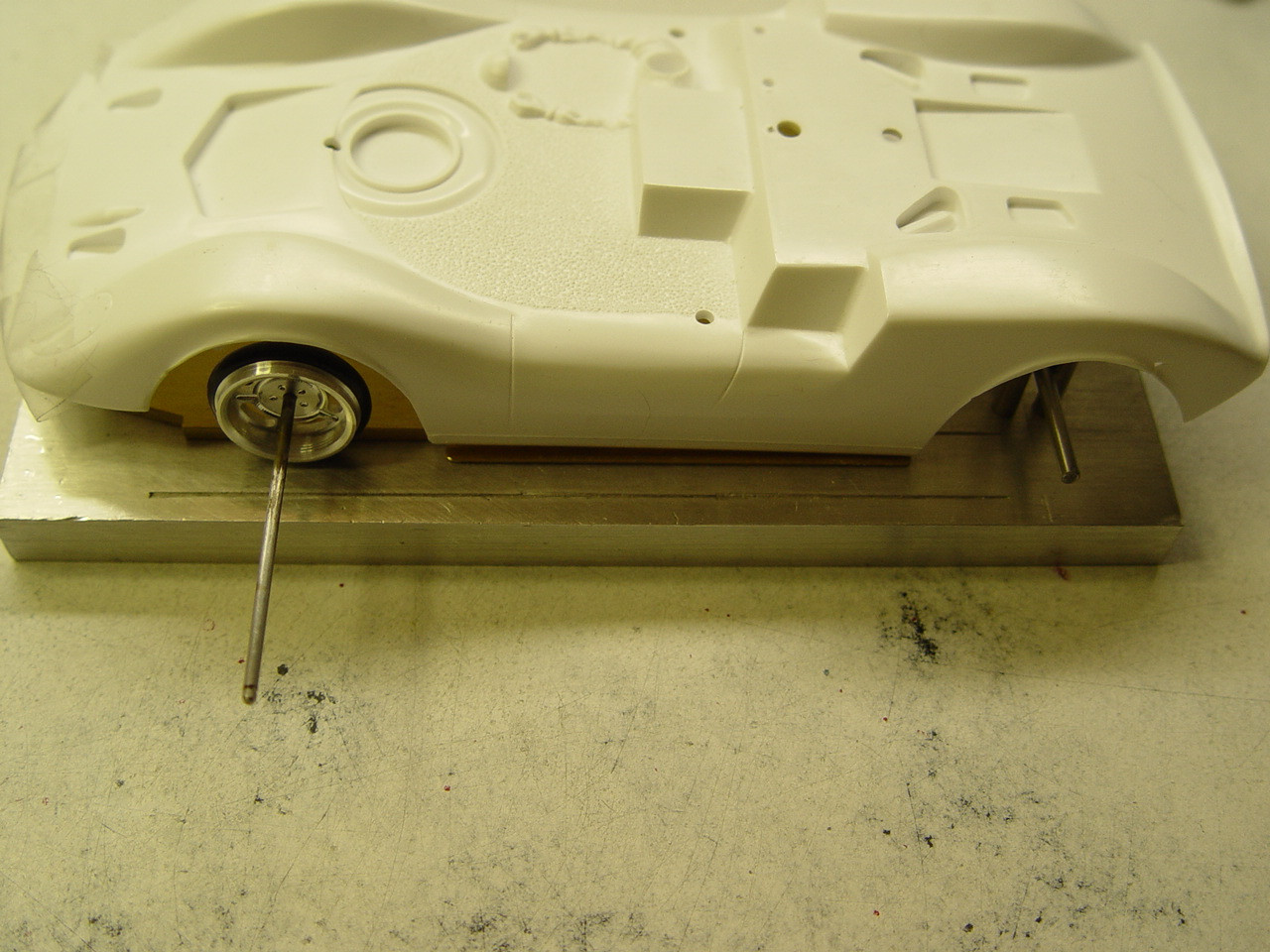
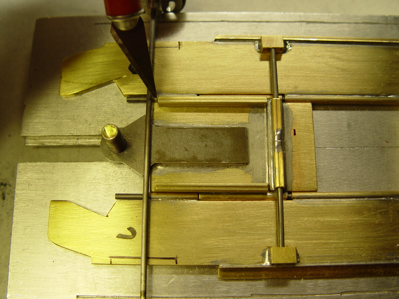
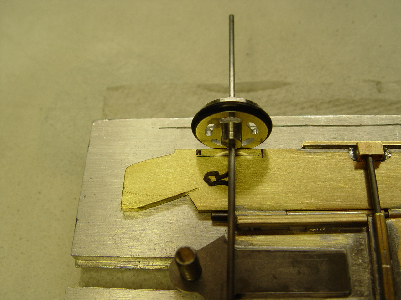
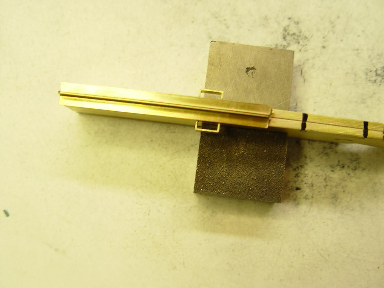
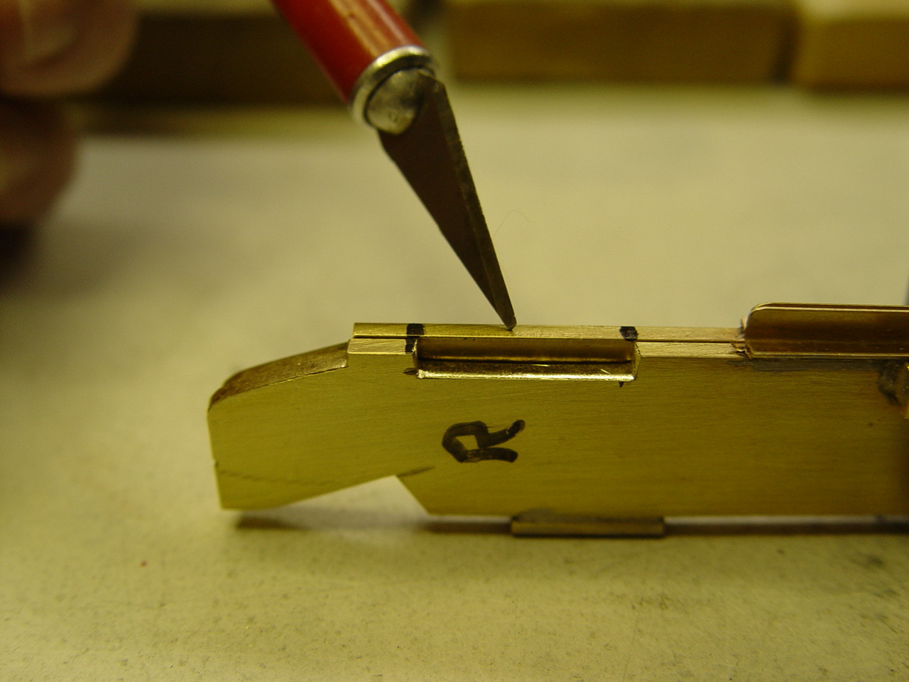
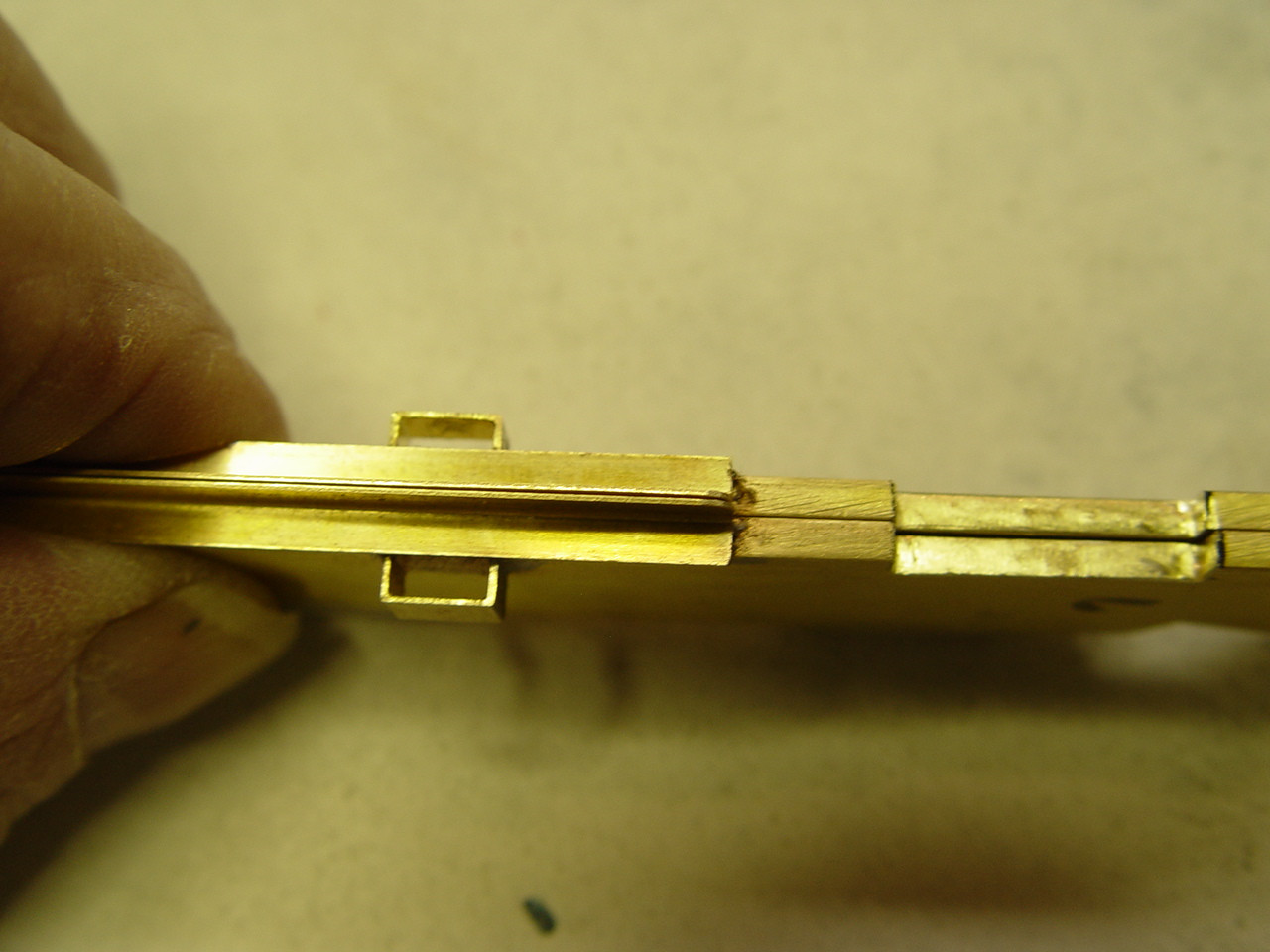
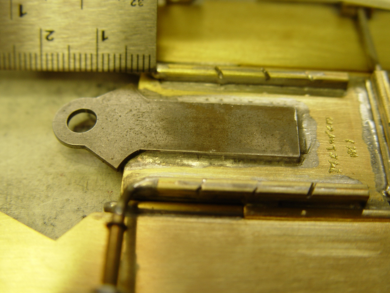
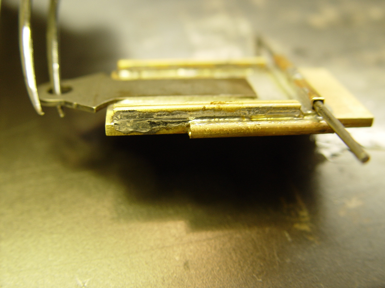
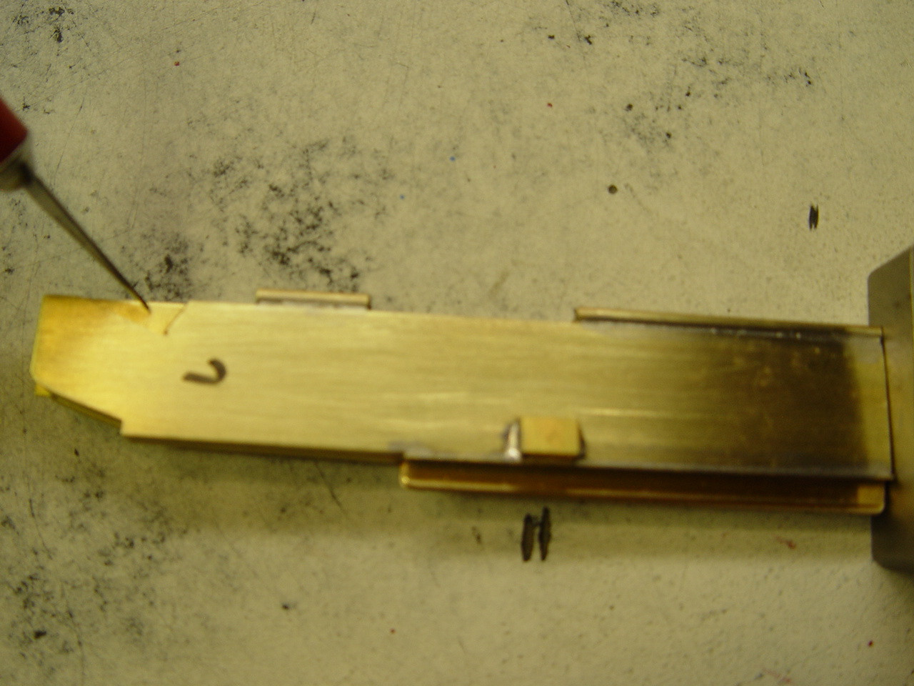
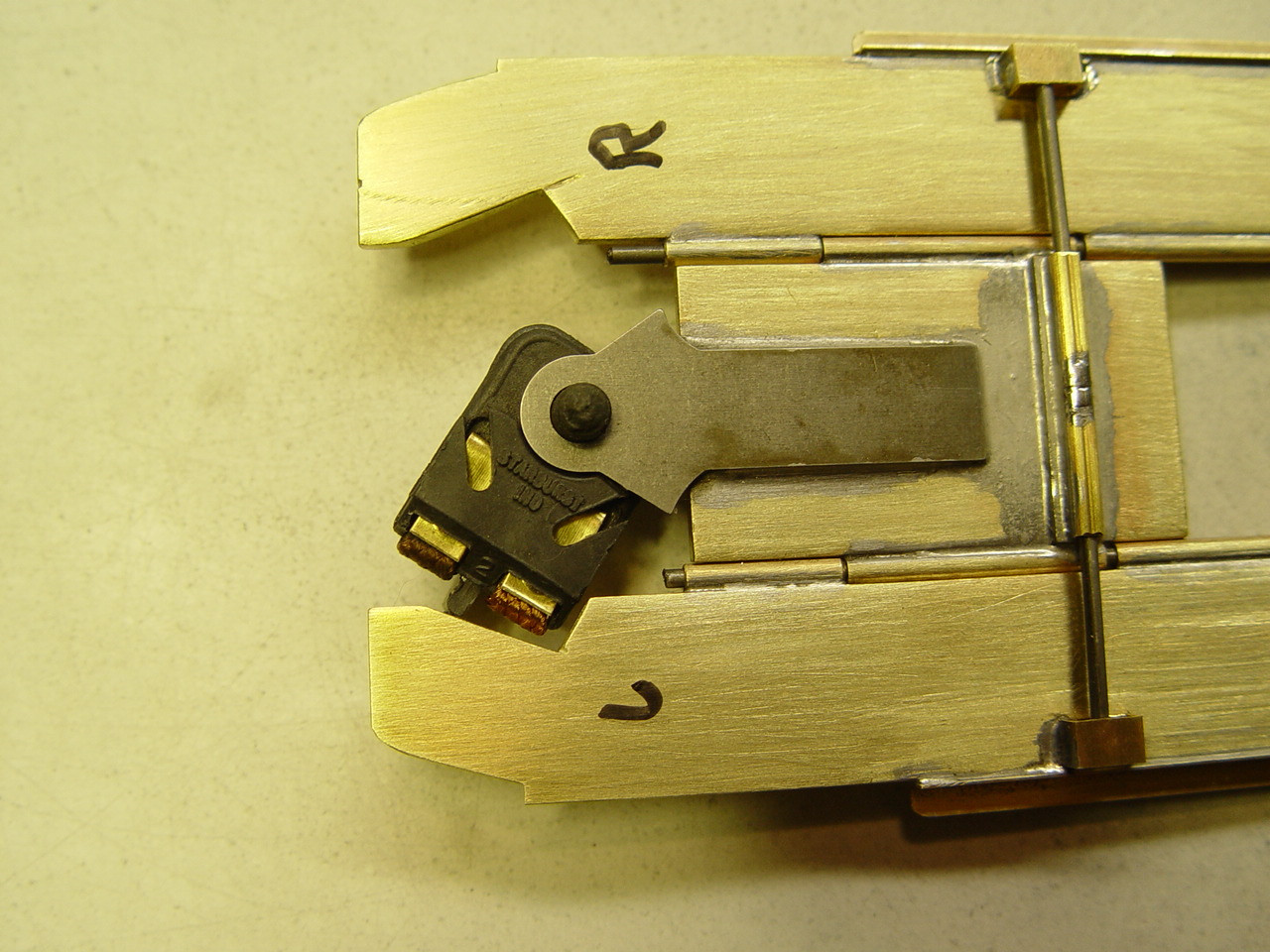
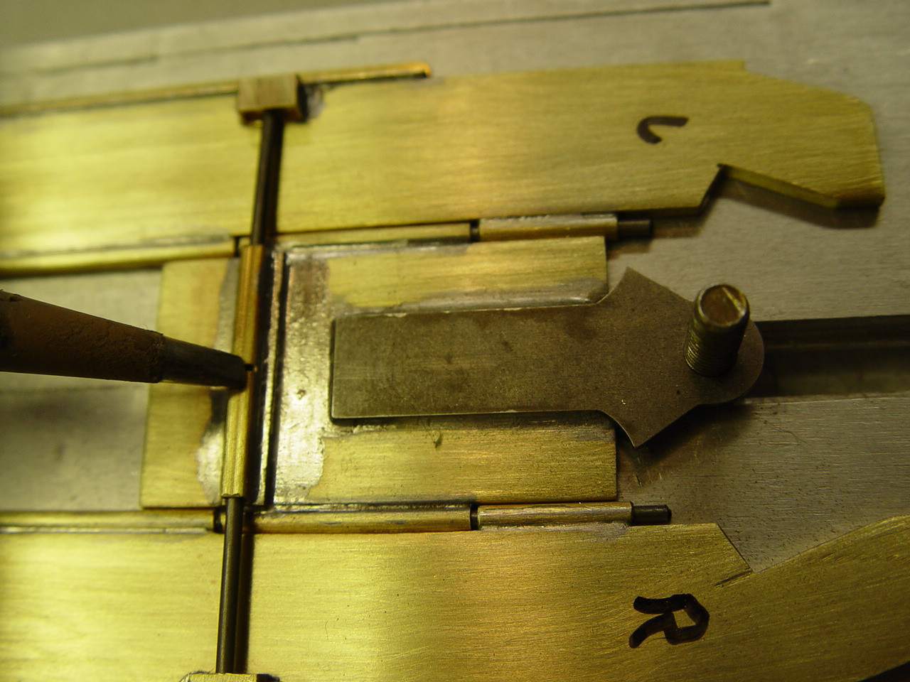
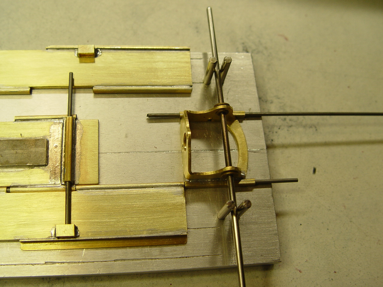
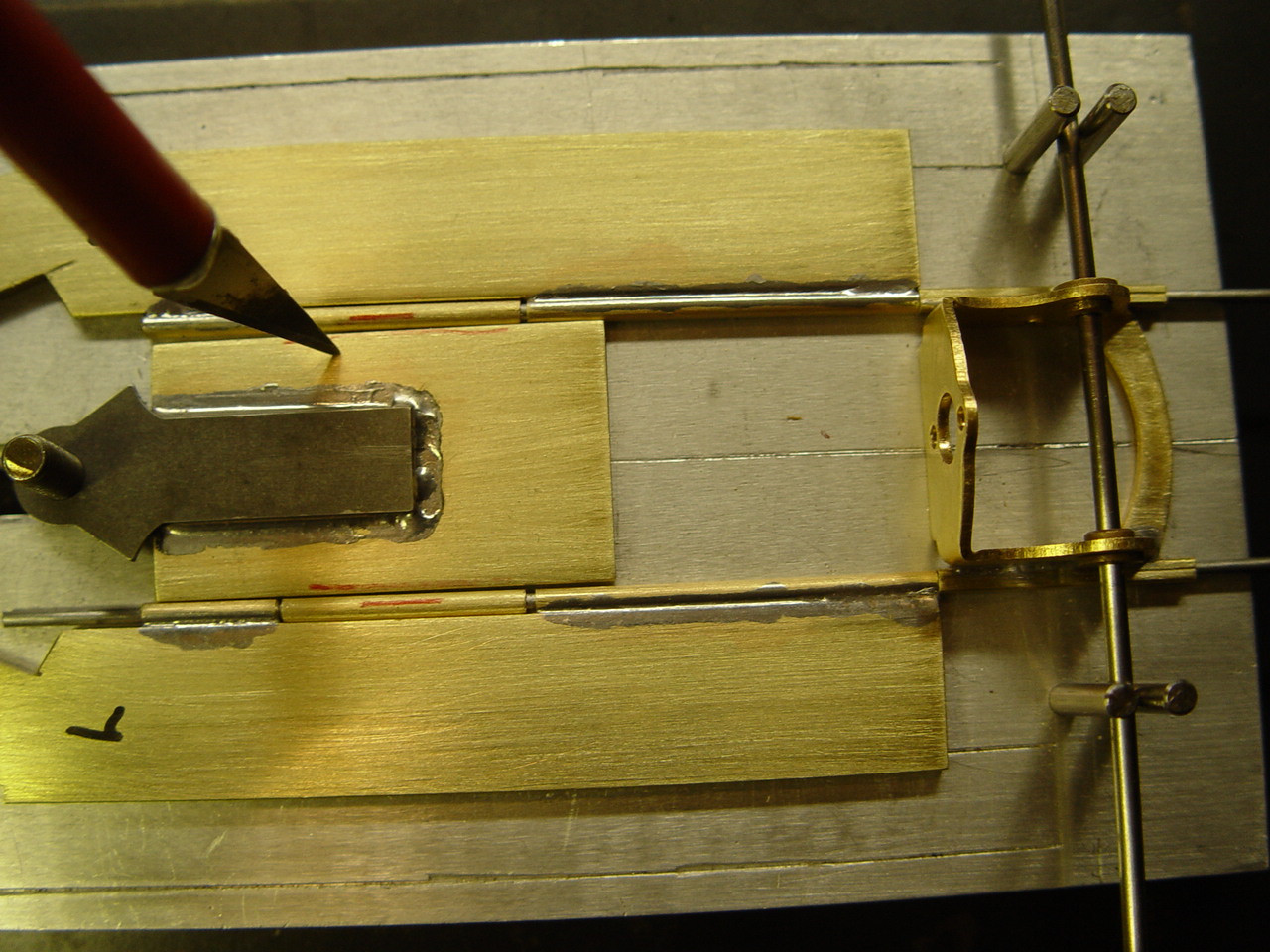
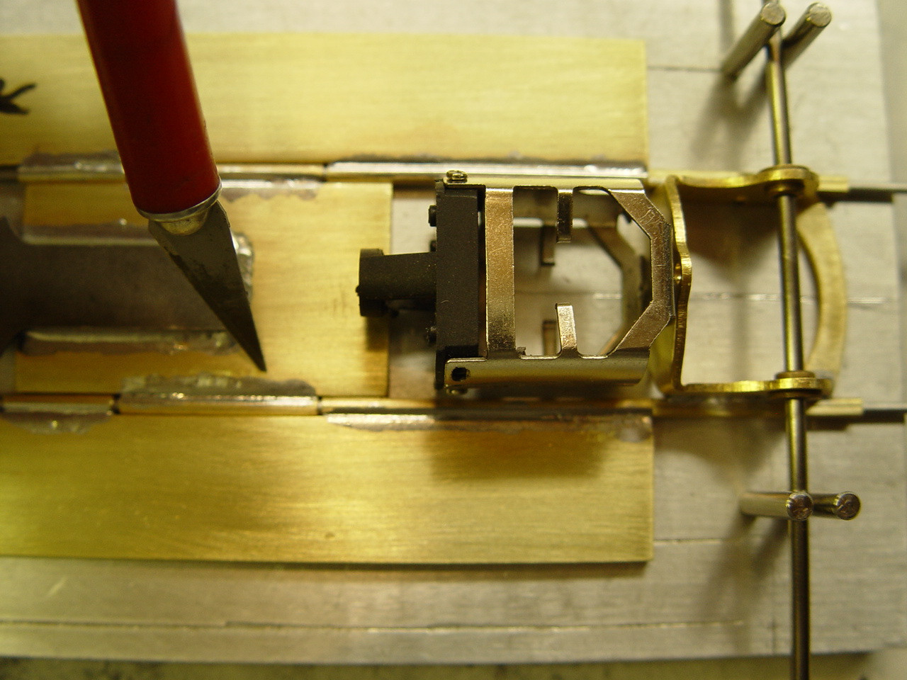
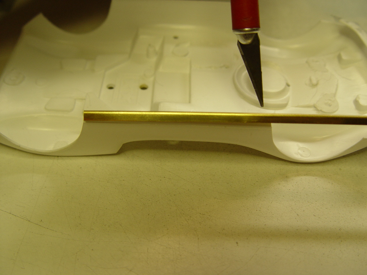
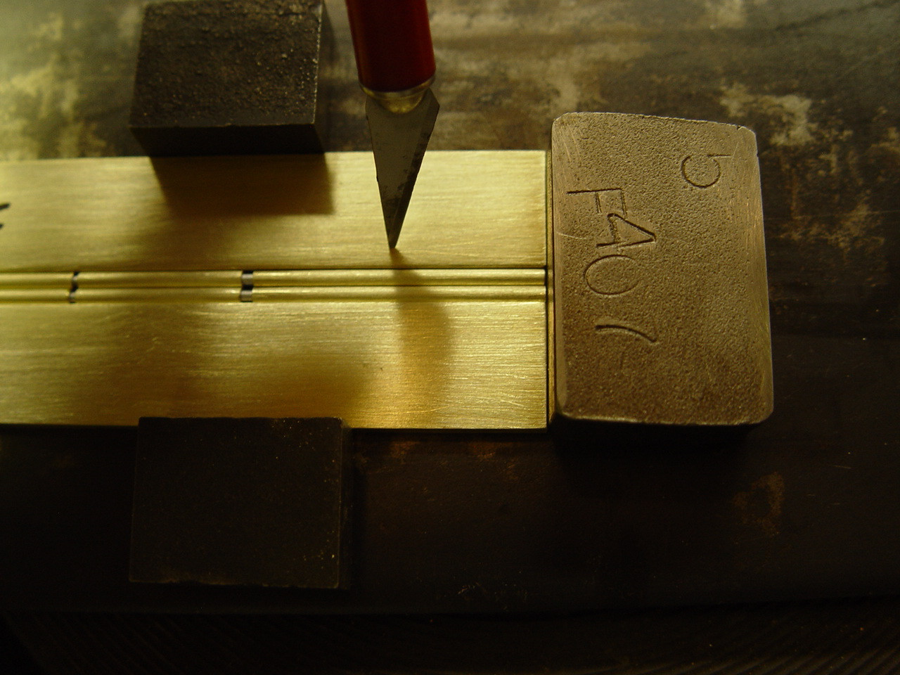
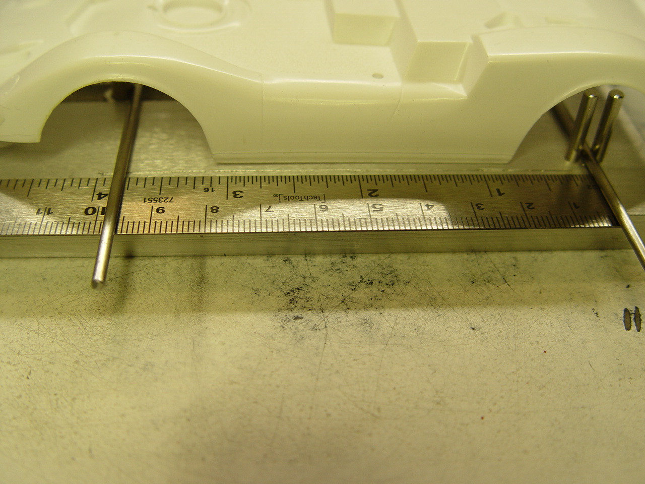
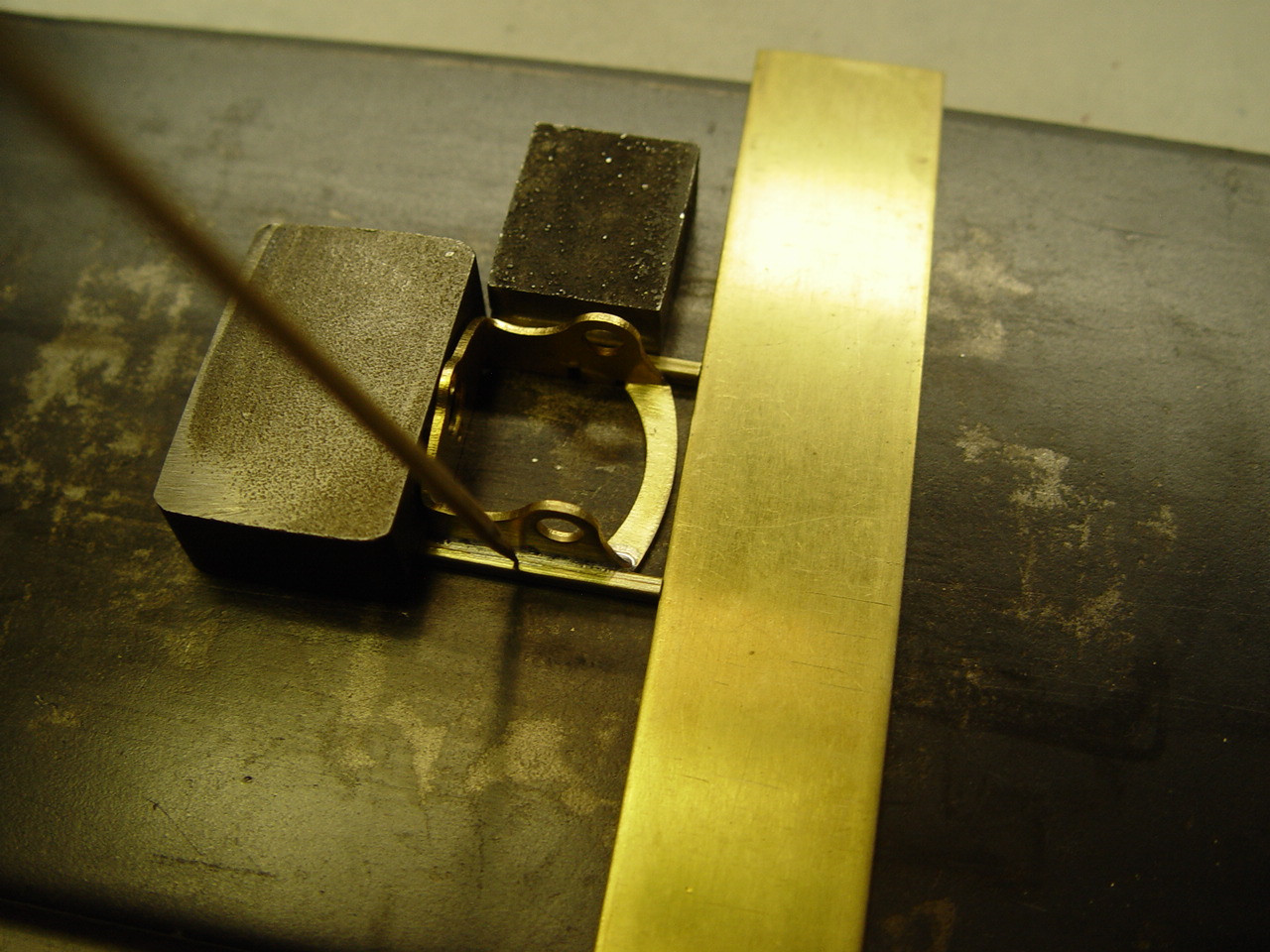
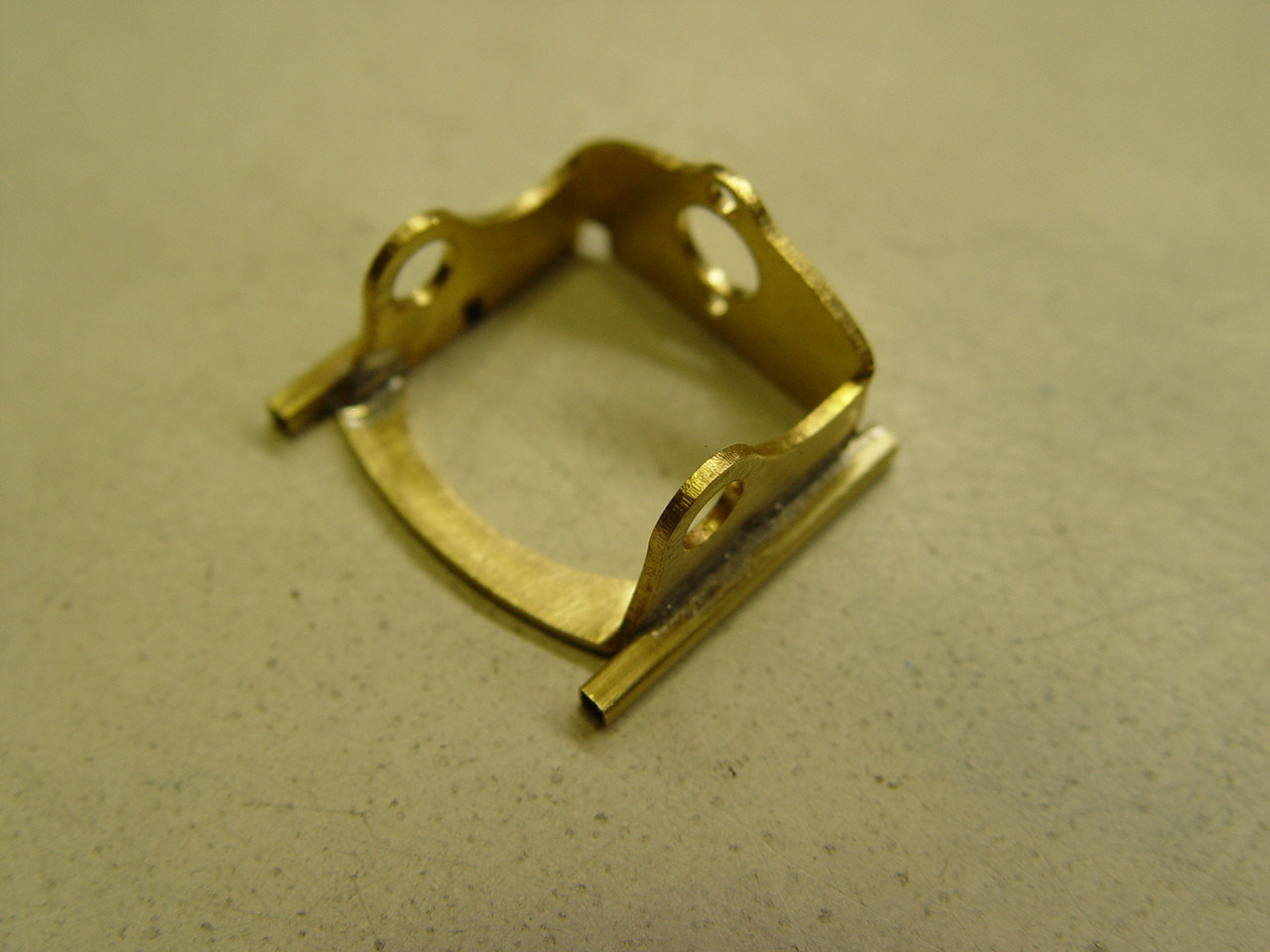
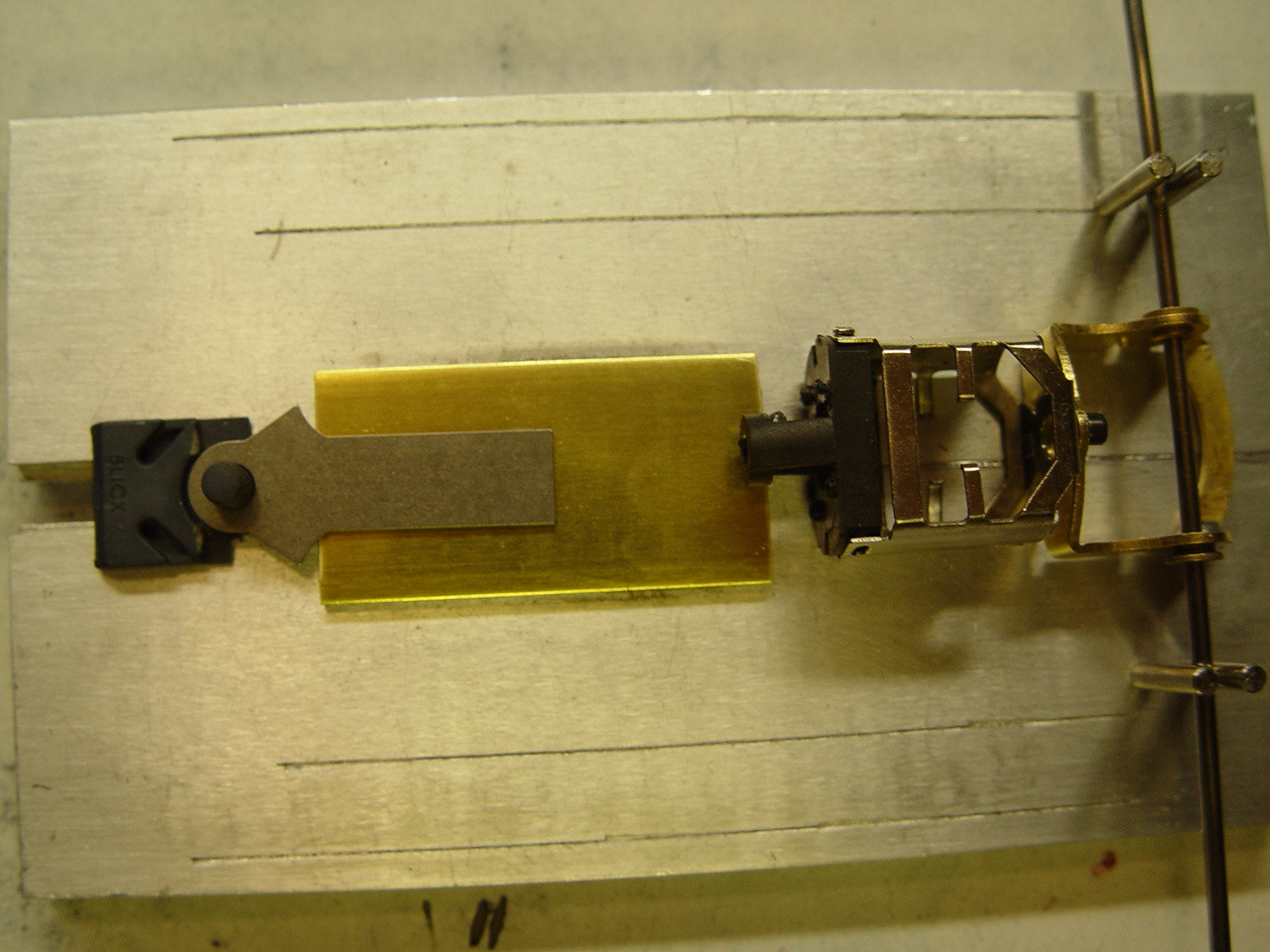
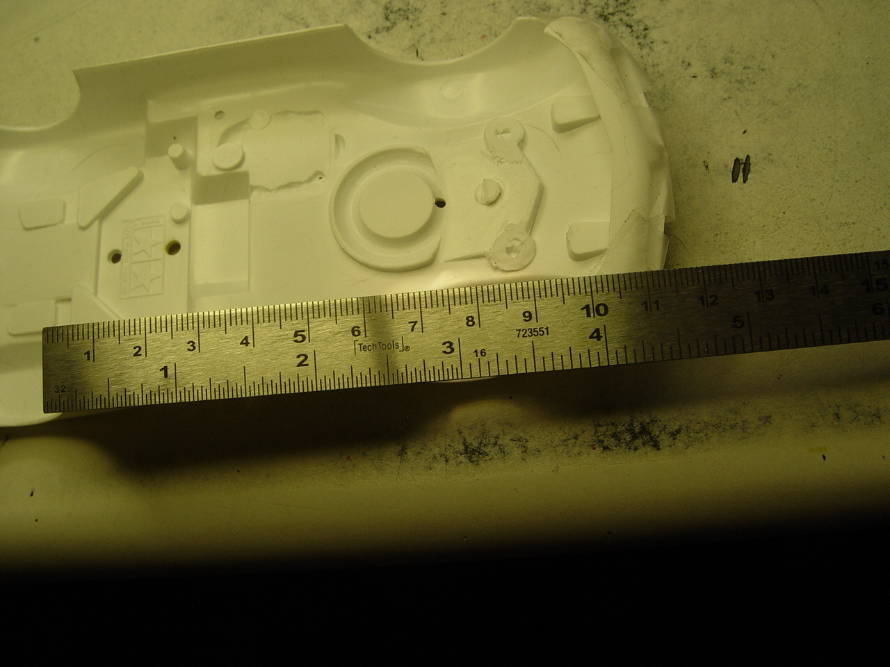
#1 place the two front wheels that you have decided to use on the build and place a .062 K&S wire install the wheels and set it on the jig. #2 Now move the center section to the middle of the two 3/32" tube as shown. #3 Place the body on the chassis so the center of the rear wheel openings on the body matches up to the rear axle. Then move the two side pans tight against the motor bracket. Rember to keep the center section centered between the side tube that you have already soldered. Now center the front wheels to the middle of the front wheel wells, as shown. #4 Mark where the front axle is set. You can place a piece of tape to hold the front axle in position. #5 Look at where the wheels are located and with a Sharpie marker draw a line from the front of the wheel to the rear of the wheel on each side pan as seen in picture 5. This measurement is about 2mm deep and 16mm long on both of the side pans. Now pull out the two side rods and remove the side pans from the center se section. #6 Cut the rectangle that you have drawn on the brass then file / sand smooth all the cuts. (the magnets are to hold the brass together in order to take the picture). #7 Now put the two side pans together and scribe the next cut on the other side pan. High lite the scribe marks if needed. Do not over cut this side pan or it will look weird. After cutting file / sand the cut area smooth. You can tape the two side pans together then file, the brass to the same length & width. #8 The cut and filed areas should look like picture 8. Assemble all the chassis parts and place what is finished so far on the jig with the side pans tight against the rear motor mount.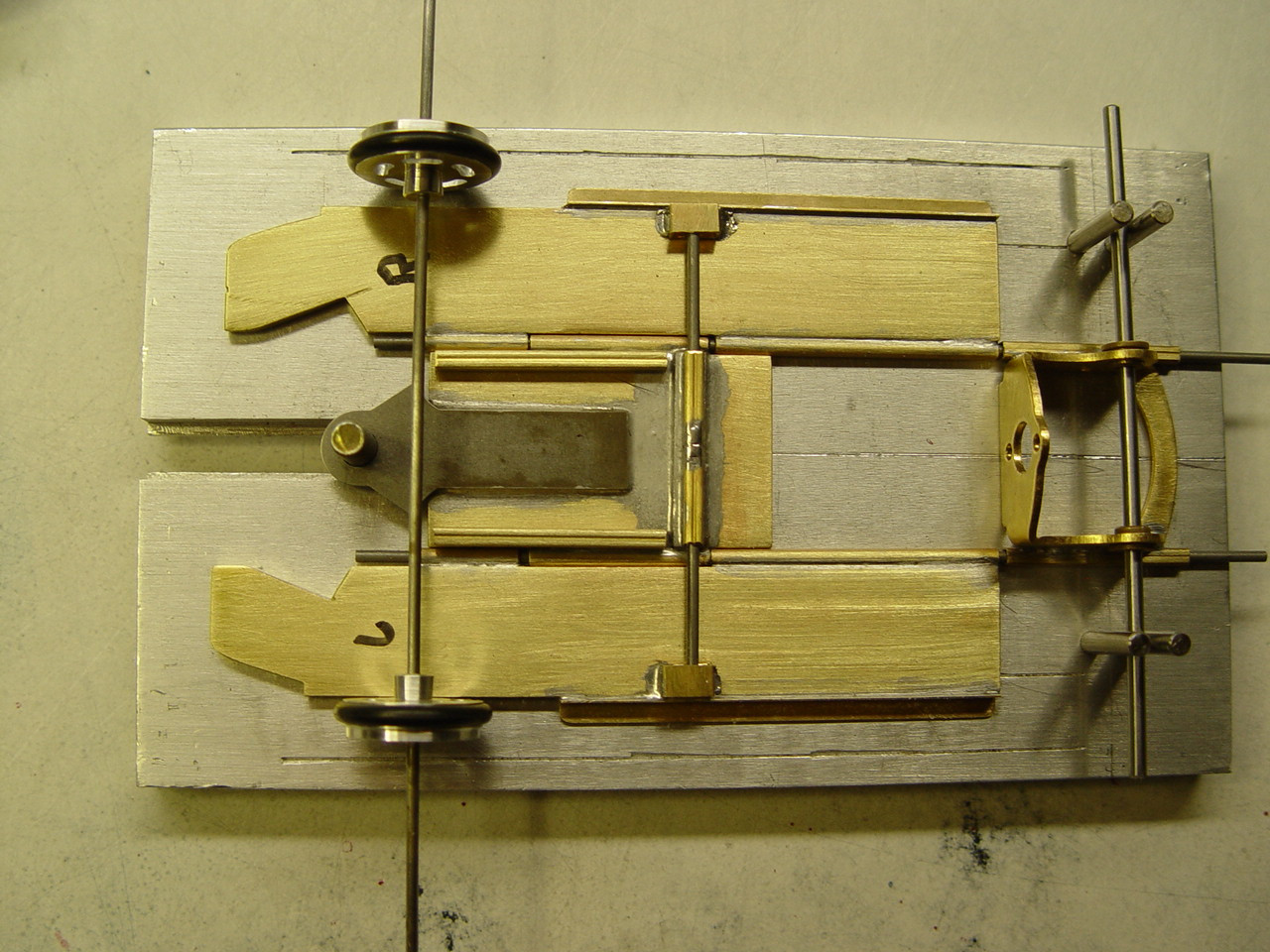
1 Yesterday 3:48 pm
Topic: Chassis Build #11 (0 replies, posted in Dust Devil's Slot Cars)
2 Yesterday 3:31 pm
Re: Chassis Build #10 (4 replies, posted in Dust Devil's Slot Cars)
No this build does not have that design. This build is the easiest brass chassis that I know of to be built for a hardbody. There are less measurements, cutting of the brass, soldering and time on the hot plate. If you build a different style brass chassis than this one = more work. There are a lot of styles, they all get harder to build. The more parts incorporated into the chassis design, the more complected they become.
This build is for a beginner or someone who just wants to build a different style chassis than what they have.
If you look at the 1/24 Scale Modifications, slot car chassis build of the month. Scroll through and see some of the different styles of builds. This build that I am showing is one that I did a write up on (#6 Chaparral 1 ). After you build a few chassis the easier, they are to build. You learn what is expected. Then you can move on to mere complected builds with confidence.
I have my Build Jig idea at the mechanist shop being built of what I think is my own design since I have not seen any others made like it. The jigs should be ready by Dec. 1, 2026. This chassis jig will make building a hard body brass chassis far easier to use than what is currently available. It will not matter what style chassis you build (easy to extremely difficult). I will post them when they get finished. Jim
3 November 17, 2026 11:11 am
Topic: Chassis Build #10 (4 replies, posted in Dust Devil's Slot Cars)
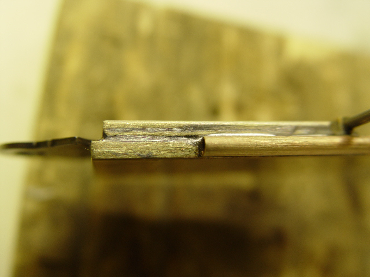
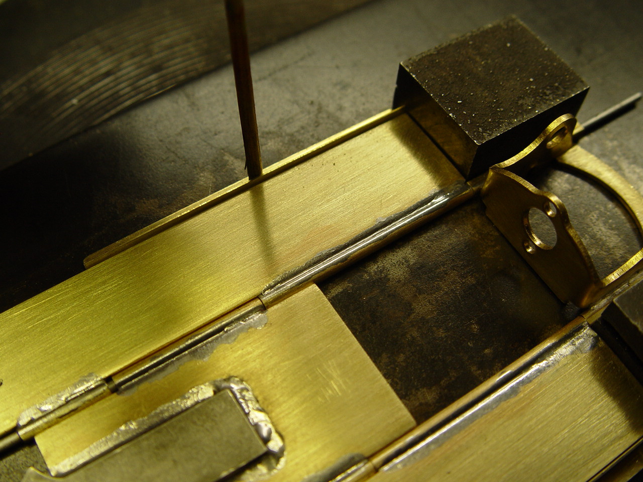
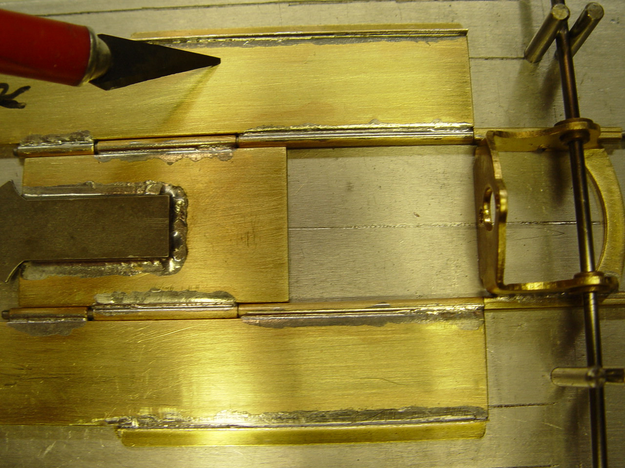
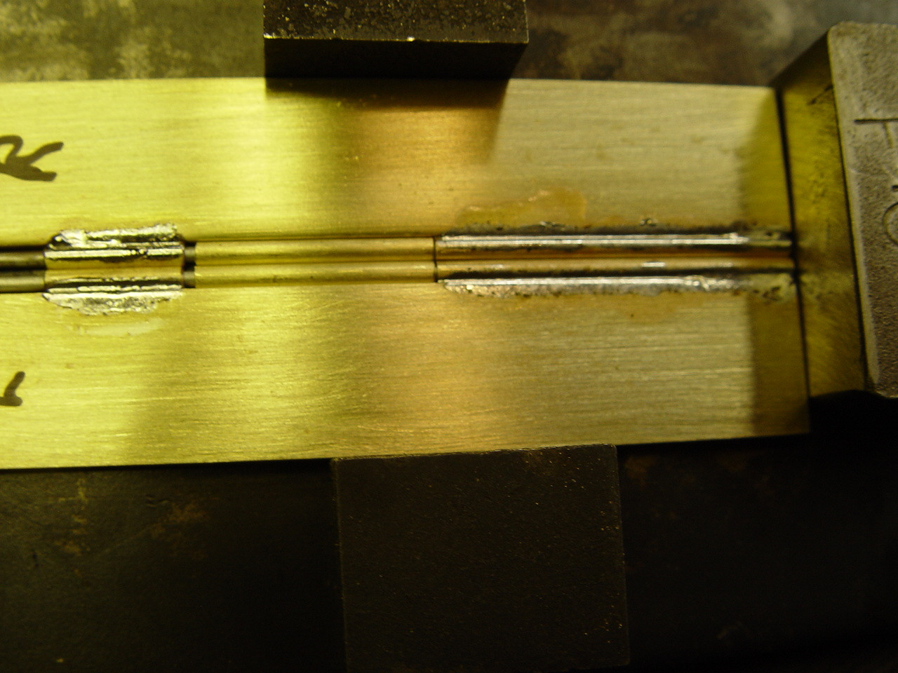
#1 Cut two equal length 3/32" square tube. #2 Place the square tube side edge on the 1" center pan and about 2.5mm from the front edge of the center pan. (as shown) #3 Lay the 3/32" square tube length about .5mm - 1mm away from the outside edge of the center section (do NOT overhang the square tube over the round tube already soldered to the center section) Hold the square tube in place with a chop stick & Solder the two insides of the 3/32" square tube to the center section. #4 Remove the center section from the side pans and place it on the hot plate. #5 Again hold the square tube in place with a chop stick & Carefully solder the outside of the 3/32" square tube to the center section as shown in picture 4 & 5 (Do not melt the solder on the round tube). #6 Clean the areas where you just finished soldering with a piece of emery cloth all the solder on the side of the center section and round tube (You should only see brass, no solder). Now clean everything with some lighter fluid and a paper towel. The center section should look like picture 6 on both sides. Clean the .063 wire with lighter fluid (Do not sand the wire) before re assembly and be sure the tube is clean and clear of any debris. Assemble everything back together on the jig.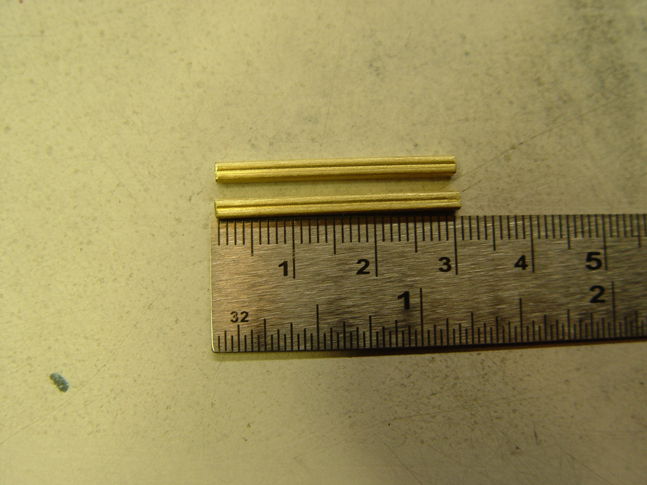
4 November 16, 2026 1:58 pm
Re: OSCAR NASCAR Race at Inslot's Checkered Flag Raceway - November 14th (5 replies, posted in OSCAR)
Thank you, Bill for all you do...
Another wonderful day at the races at Bill's track. It was great to see and talk to everybody again. Good times had by all. I do agree we need more hard body races.
5 November 16, 2026 1:41 pm
Re: Chassis Blocks & Jigs for Scratch Building (13 replies, posted in Modifications)
Bill all your pictures have vanished since before Halloween? Did the internet Halloween monsters eat the jig block pictures?
Jim
6 November 10, 2026 7:25 pm
Topic: Chassis Build #9 (0 replies, posted in Dust Devil's Slot Cars)
Read this page before going any farther and understand what needs to be done. You have seen in some of the previous pictures the two cuts were already made. That is because I forgot to take some pictures during the writing. It will not be a problem. Do not cut or round the side pans ends yet. This will come later.
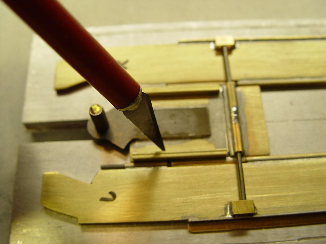
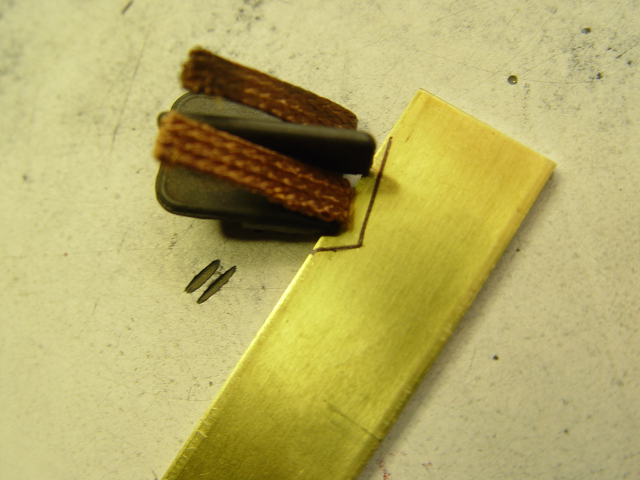
#1 Hold the chassis as shown with the brass center pan pushed forward with your thumb. Now with the guide and braid in place then position the guide stop at the tongue. Now mark with a scalpel knife an odd-looking V-shape on each of the brass rails. As shown in picture one. #2 you can mark the shape with a sharpie marker, now you can now see where to cut a bit more easily.
You can disassemble the chassis by pulling out the two steel rods to make the cuts a bit easier.
You will somehow need to hold the brass very steady. (Options) You can put the brass side pan in a vise with a wet towel or with a wet towel and vice grips on a section of wood so you do not mar the brass and helps to keep the brass from slipping, then cut with a Dremel with a cut off wheel attachment, or use a jig saw or band saw with a metal cutting blade, or a metal file or whatever you think will get the cut done without any injury to yourself.
("Danger - Will Robenson - Danger"). Caution, Think this step through before making any cuts in the brass. Do not hold the brass with a wet rag while cutting the metal. If any of this makes you feal uncomfortable, talk to someone who has cut metal before and get an idea of what is going to be needed to do this step.
Now slowly and be careful - cut the odd V-shape into the brass. #3 Once you finish the cutting the first brass side rail, you can put the L/R brass flat sides together with a flat block at the back of the side pans to keep them equal length, you can use tape to hold them together to make your scalpel mark in the second brass siderail and see if the marks are even. then hi-lite with a Sharpie mark on the next side pan to be cut. Cut the odd V-shape in the second pan. Now flat file / smooth then camphor the sharp edges with the file or emery cloth top and bottom on both side pans.
#4 You can see what the finished cut brass needs to look like in the pictures of each step.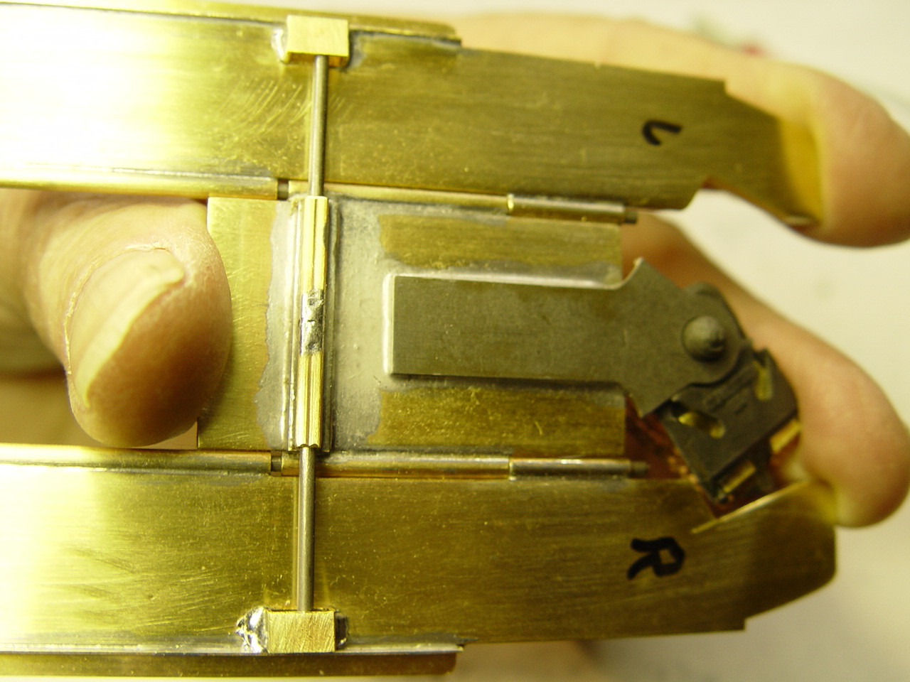
7 November 9, 2026 7:30 pm
Topic: Chassis build #8 (0 replies, posted in Dust Devil's Slot Cars)
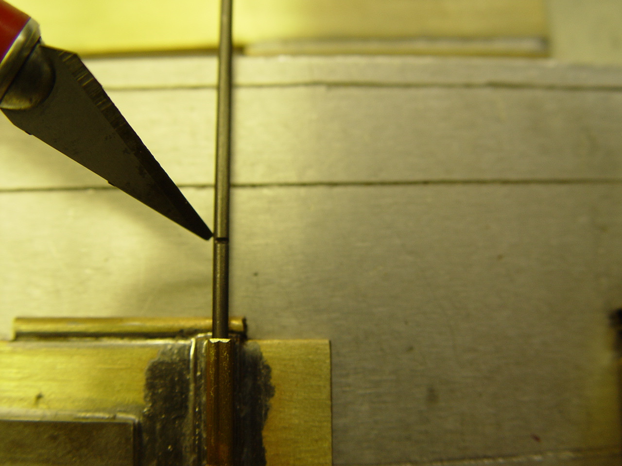
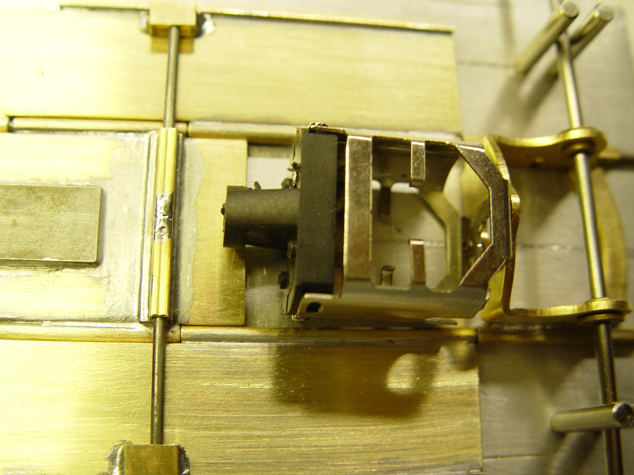
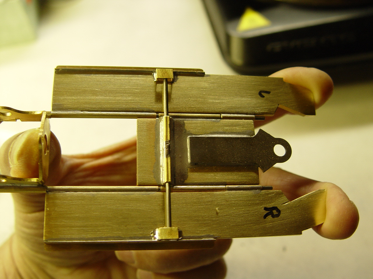
#1 Assemble all the parts on the jig and center the steel rod between the two side pans. Now make a small cut with a dermal in the center of 3/32" square tube as shown do Not cut too far, when you see a spark, you have cut far enough. #2 Remove one side pan and remove the steel rod and sand it only in the middle area of the little cut mark. Then reassemble all the chassis parts back together on the jig. Now alien the steel mark to the square brass cut section, be sure the steel rod is still centered to the outer pans. If the steel rod moved a bit, that is still o.k. #3 Turn on the solder iron, put a dab of flux in the cut opening and seal the cut area closed with solder. #4 Clean the area of the solder marks. And lay the motor housing against the motor housing. As you can see, you are well ahead if any obstructions. #5 Now you can pick up the chassis off the jig and the side pans will not fold, although they will move up and down slightly. If you hold the front side pan rails together against the motor bracket, the center section will also move back and forth as shown. (so far so good).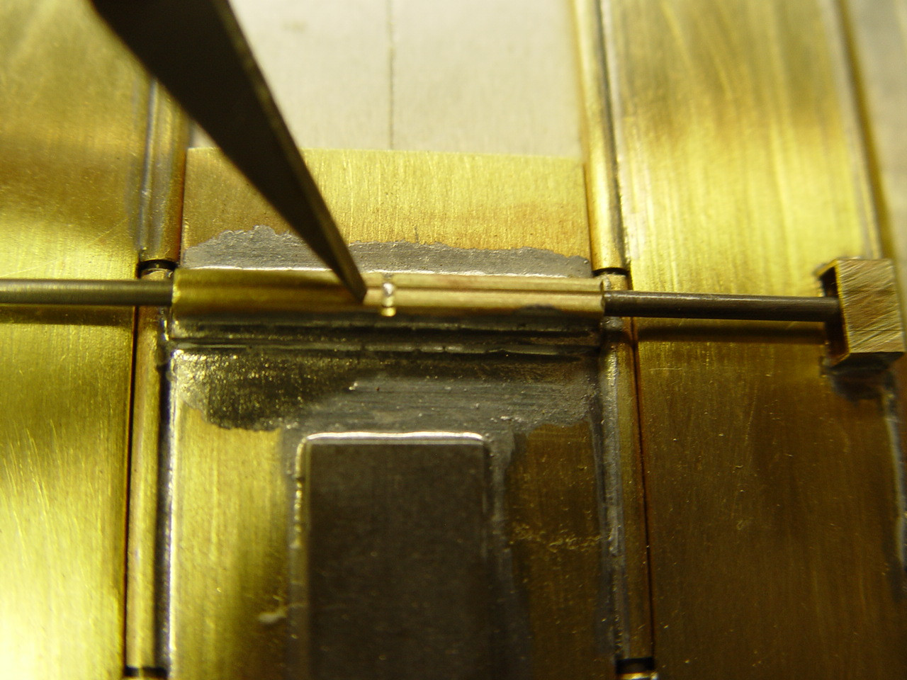
8 November 9, 2026 7:20 pm
Topic: Chassis Build #7 (0 replies, posted in Dust Devil's Slot Cars)
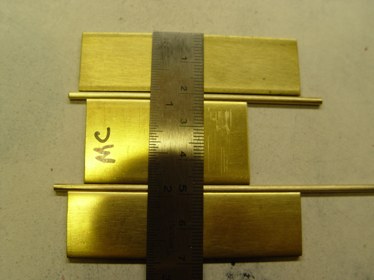
#1 You will now need to cut a brass flat K&S #8242 - .032 1" long x 8mm wide top right of the ruler. Then cut two K&S rectangle #8264 at 8mm wide equally top left above the ruler. Then cut a 1" section of K&S 3/32" square tube at the bottom of the ruler. You will also need to cut a piece of .063 wire 68mm long not shown. Sand all the brass top sides bottom and be sure to remove all the burs and cut all the tubes clear so the steel rod will pass through easily as pictured. Do not sand the steel rod.
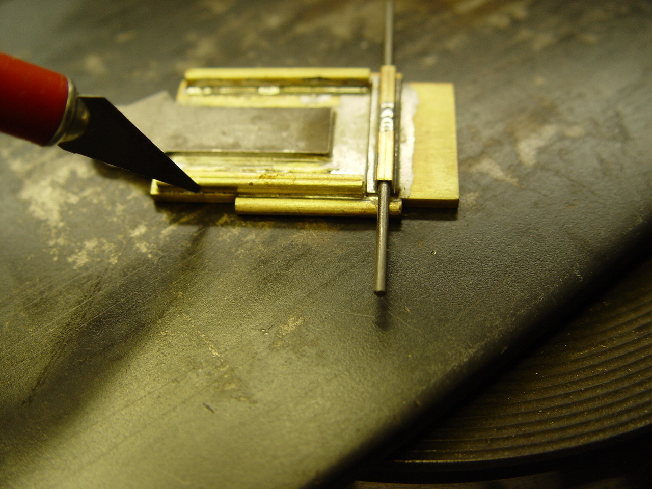
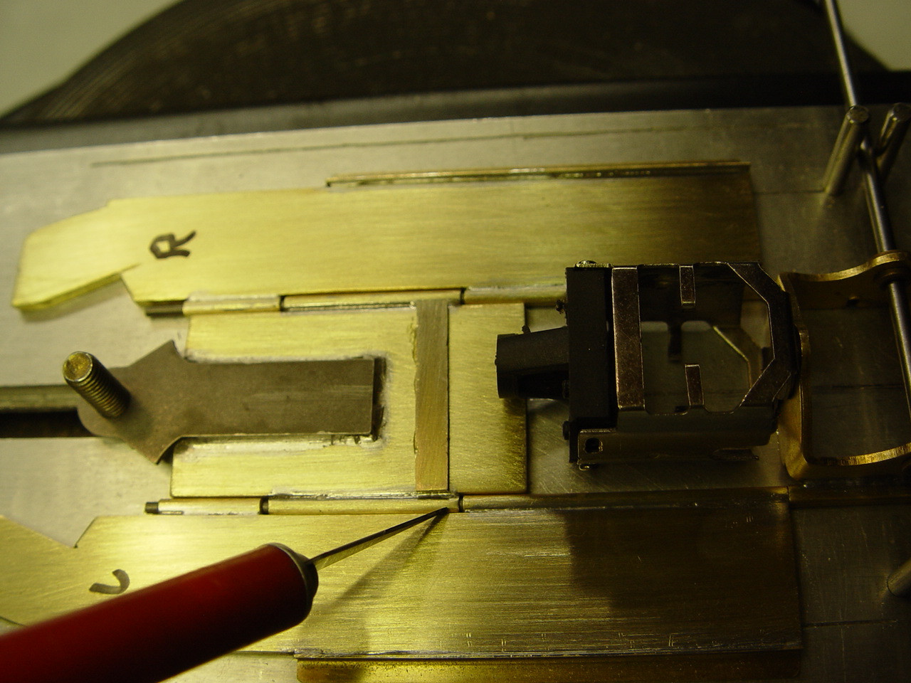
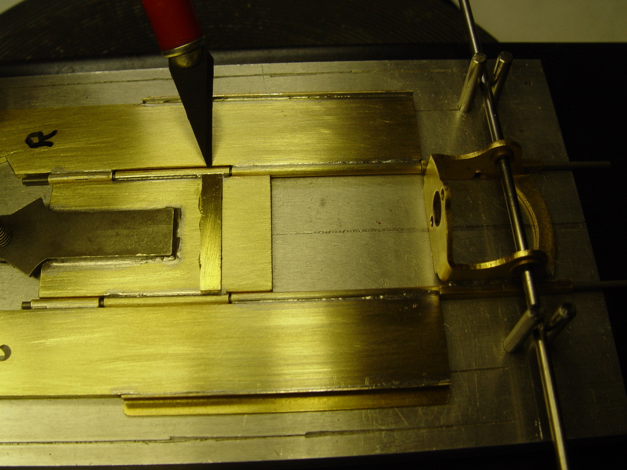
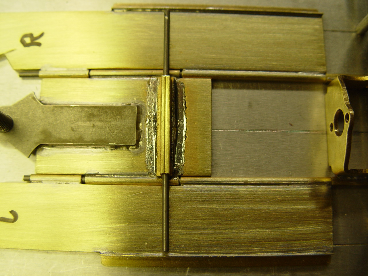
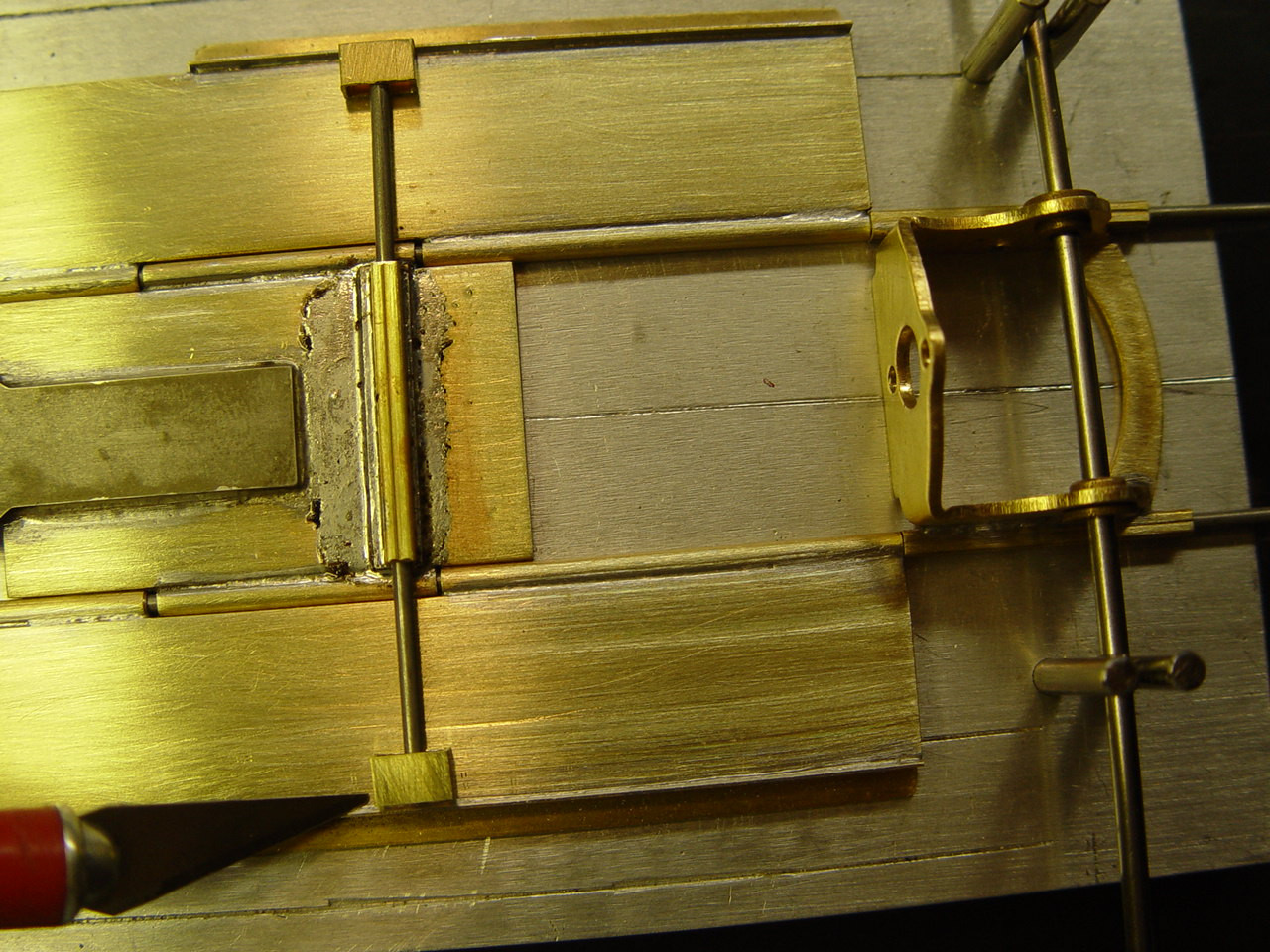
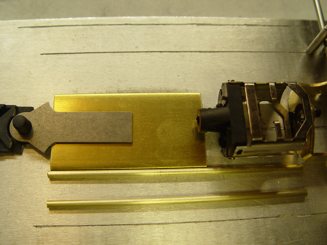
#2 Place the flat 8mm brass on the center section with a smear of flux on the bottom as shown and ahead of the end bell. Remove the motor housing from the area. #3 Make sure that you move the tube on the center section an equal distance front and back on the side brass tubes as shown. Now solder the 8mm brass section to the center section as shown. #4 Now put the steel rod through the 1" square tube and place on top of the center of the 8mm flat brass that you just finished soldering. After soldering, the chassis should look like picture 4. Be sure you keep the side rails tight against the motor mount. #5 Keep the tubes centered again. Now put the rectangle at each end of the .062 rod centered to the rod as shown. Put a bit of flux at each end of the rectangle and solder the two ends of each rectangle as seen in picture 6. #6 You can now remove the two rods and clean the two side pans and center section of all the excess flux with some lighter fluid and a piece of paper towel. If you have some excess solder on the brass, you can sand that away also.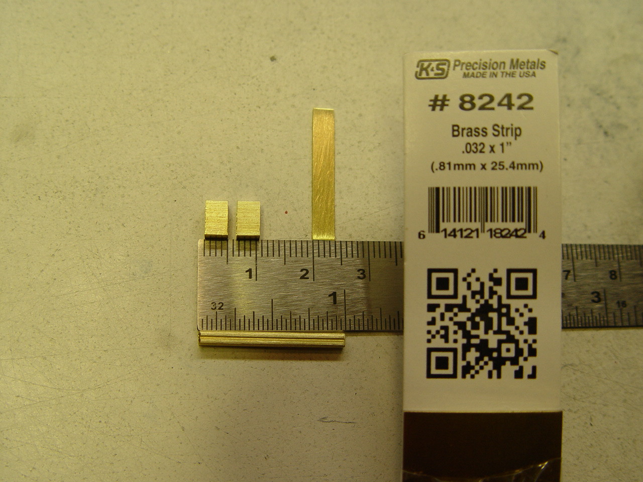
9 November 8, 2026 9:51 pm
Topic: Chassis Build #6 (0 replies, posted in Dust Devil's Slot Cars)
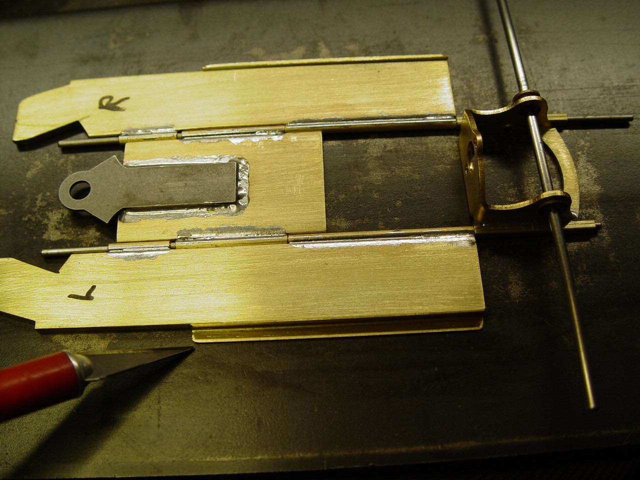
#1 Take the side pans off the wire and flat file the space between the two soldered tubes using a small flat file. Then file back and forth about 6-8 even passes between the two tubes this needs to be done on both side pans. This step will allow the side pans to move with less friction. #2 Place both side pans back on the wire on the jig and square everything tight and the side pans against the motor bracket. Make an equal gap between the two soldered pieces of pipe as shown. Next, you will need to solder the unsoldered tube sections to the center section of the chassis marked in red. Place the jig on the hot plate, turn on and get everything up to operating temp. Make sure the gap is equal on both ends of the tube. Now solder the two tube sections to the center section marked in red. You may need to hold the side pans tight against the center section, if you see a gap. Do not get any solder or flux in the tube or on the wire. When you are finished soldering turn everything off. #3 Clean the solder joints you just soldered. This is what the end result should look like after being soldered. The center should move freely between the two tubes. If not, you will need to see what went wrong and fix it. #4 Cut two pieces of K&S brass angle part # 9880. Make a measurement then mark at the edge of the wheel well on the brass at the side if the body then cut the brass. The two cut pieces will be the shelf for holding the body on the chassis. The two pieces should measure 6mm each equal length. #5 Sand both of the two outside of the brass angle, then sand the outer edge of each side pan. Round the angle corners front and back so they are not sharp. #6 Place each of the angles flat against the side pans as shown, use a magnet or metal block to help keeping it from moving. When ready, hold down the angle flat against the side pan and flat on the hot plate metal with a secure or chopstick. Solder the brass angles to the side pans and use some flux when soldering. #7 Clean the solder area with some lighter fluid and a piece of paper towel and it should look something like this, picture 7. 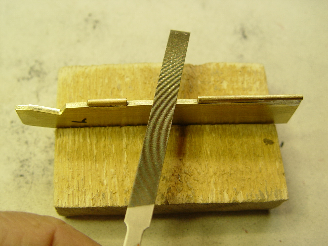
10 November 8, 2026 9:32 pm
Topic: Chassis Build #5 (0 replies, posted in Dust Devil's Slot Cars)
Before starting this section and all the rest of the build, read the page & view the pictures first before going on, so you will know what to expect...
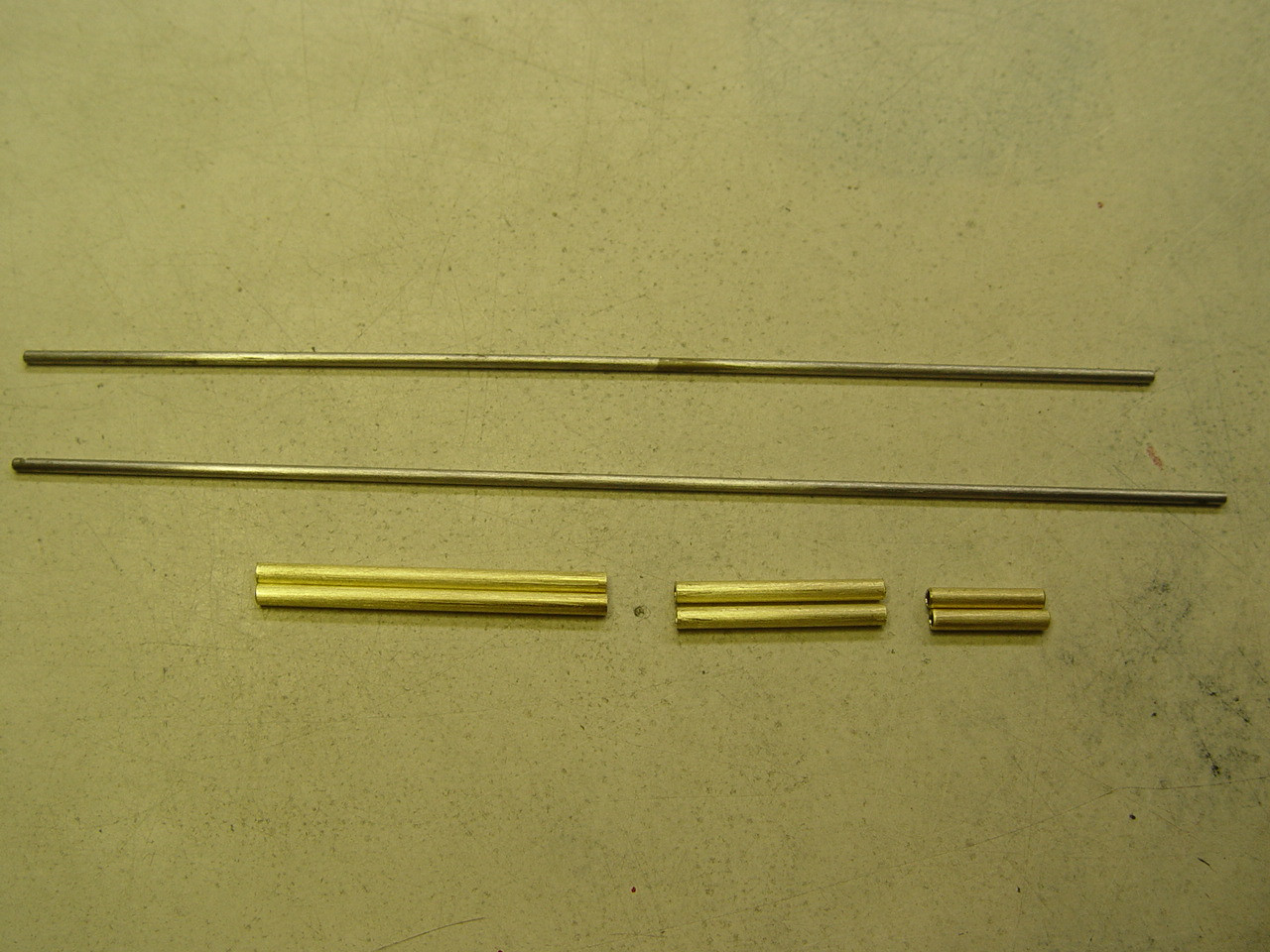
#1 put all the brass on the jig and a line everything square to the motor bracket. With a sharpie, make two marks on the 3/32" brass tube as shown. Cut the tube at the two marks for each side. Clean the ends of the tube so the .063 wire will move freely through tube. #2 You will have two of each size tube cuts, with three different lengths of tube. Now cut two .063 K&S wire pieces at 5 inches each, wipe the wire with lighter fluid and a paper towel, do not sand the wire, that comes later. You can see how dirty the paper towel got after cleaning the wire. This is why it is very important to clean / sand everything before soldering. #3 Put together the .063 wire in the tube, long, medium to short, Place the longest tubes closest to the motor bracket, then place the assembly in-between the two equal lengths of brass side pans as shown. Now block the parts together with metal blocks or magnets as shown. Leave a gap between the tubes as shown, your discretion how much you want the body to move back and forth. turn on the solder iron and the hot plate, let the parts heat to operating temp. (do not forget the 1/4" plate on top of the hot plate to disperse the heat evenly). Remember do not bump anything. #4 You are now ready to solder the outside edge of the tube to the inside edge of the brass (bat wing). Do not solder the middle tubes. #5 After soldering his is how it looks with an equal gap between the tube on each side, after step 5 Turn everything off. Clean off the solder flux on the brass. #6 The tube with the .063 wire should move freely. Put all the parts on the jig and line it up square. If everything lines up square, all is well. If not, you will need to find the problem and fix it.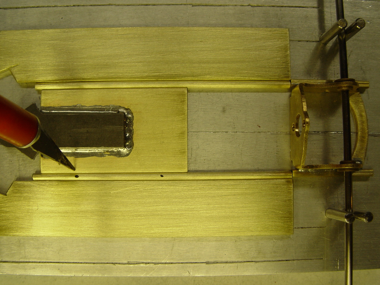
11 November 8, 2026 9:19 pm
Topic: Chassis Build #4 (0 replies, posted in Dust Devil's Slot Cars)
Before starting this section and all the rest of the build, read the page & view the pictures first before going on, so you will know what to expect... The pictures used are a visual aid only and NOT used for any measurements.
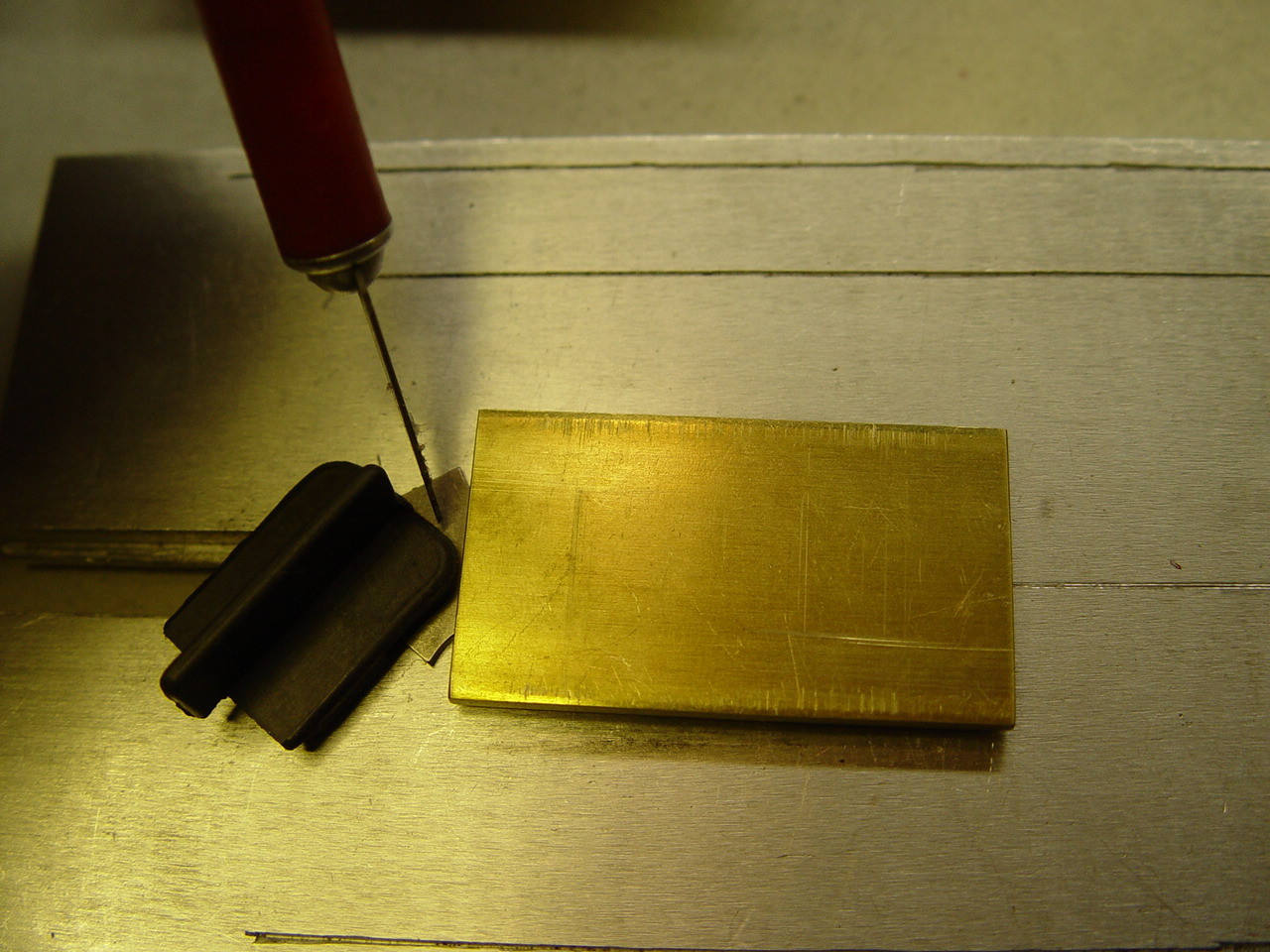
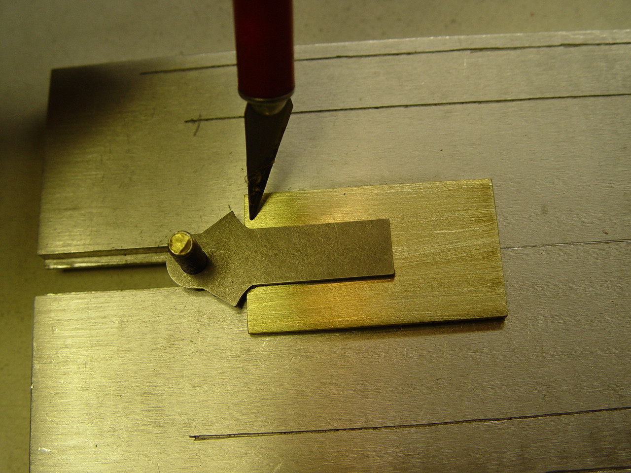
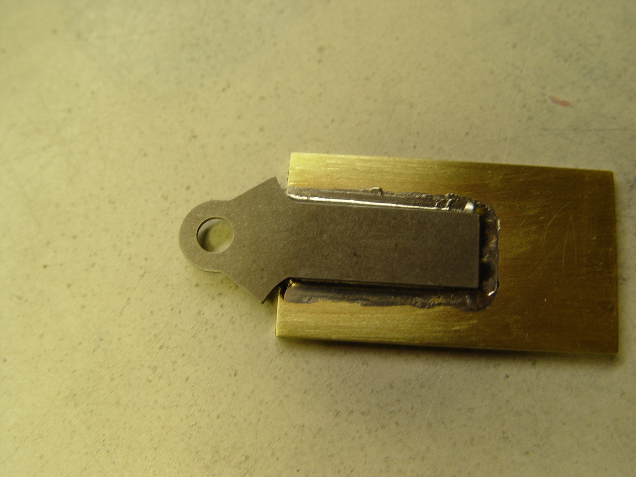
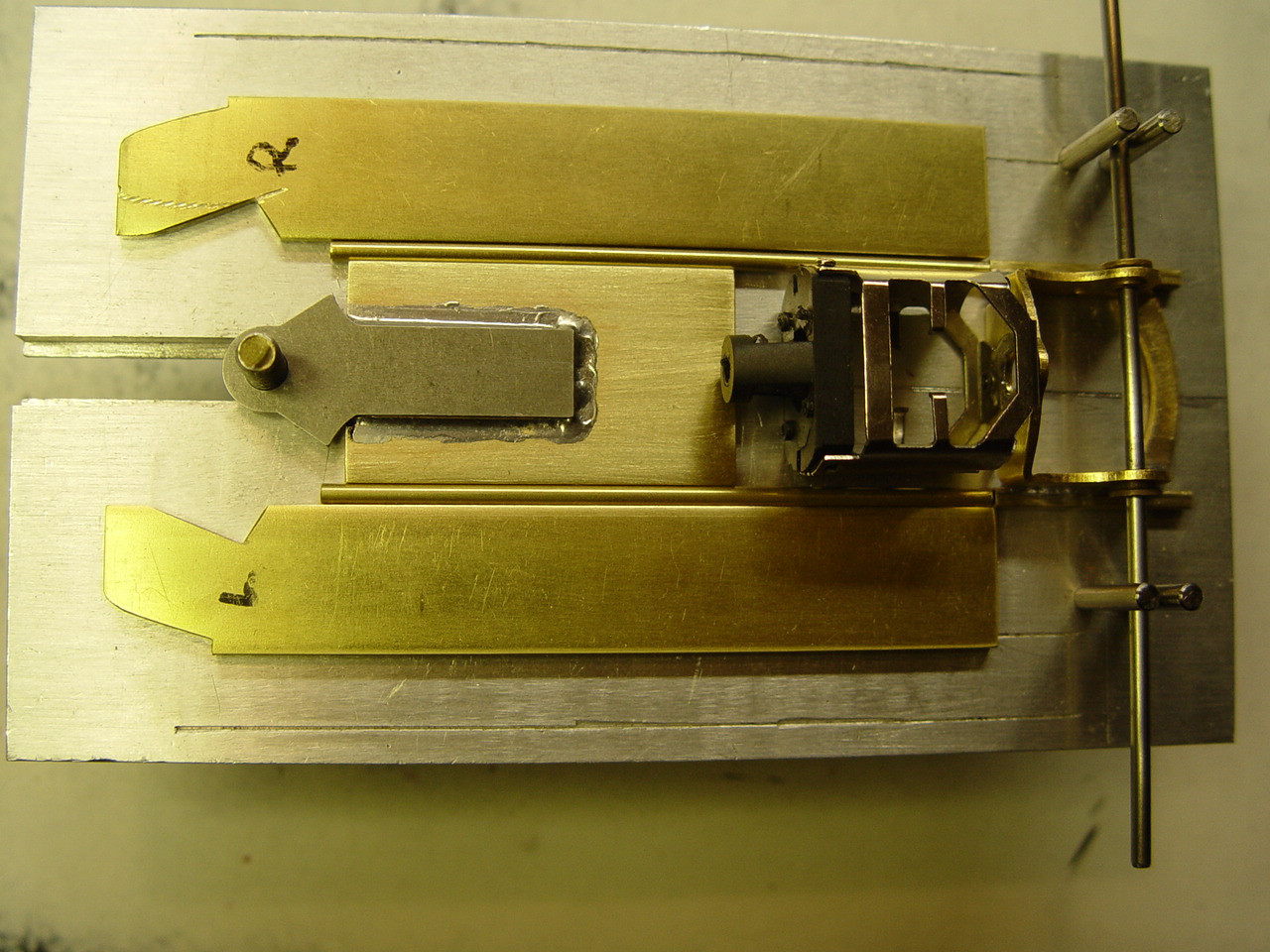
#1 Sand the top side and sides of the brass 1" center and the bottom of the tongue and sides, do not sand the top of the tongue. I take the Dremel and cut light groves on the bottom of the tongue so that the solder will flow under the tongue while I have pressure holding the tongue down while I am soldering. #2 Turn everything over and hold the tongue to the brass and measure the distance from the guide to the edge of the brass so the guide will operate freely in the turn position. #3 Turn the parts over (remember sanded sides together and put a small smooth amount of solder flux between the tongue and brass. Put the two parts on the jig. Position the tongue on the brass at the measured distance that you chose. Center the tongue on the brass. (make sure it is centered.) Place the jig on the hot plate and turn on the solder iron and the hot plate, let the two heat to operating temp. (do not forget the 1/4" plate on top of the hot plate to disperse the heat evenly). Remember do not bump anything. You can hold down the tongue with a chopstick while soldering. Add a small amount of solder flux to the three sides of the tongue then solder the three sides of the tongue to the brass. When finished soldering, turn everything off. #4 Remove the part from the jig then let cool, then clean the parts with lighter fluid and a piece of tissue /paper towel removing all the solder flux from the brass and tongue. The soldered parts should look something like picture 4 with the tongue centered on the 1" brass center section and overhang for the guide to move freely. #5 place everything on the jig and see if everything is straight and square. 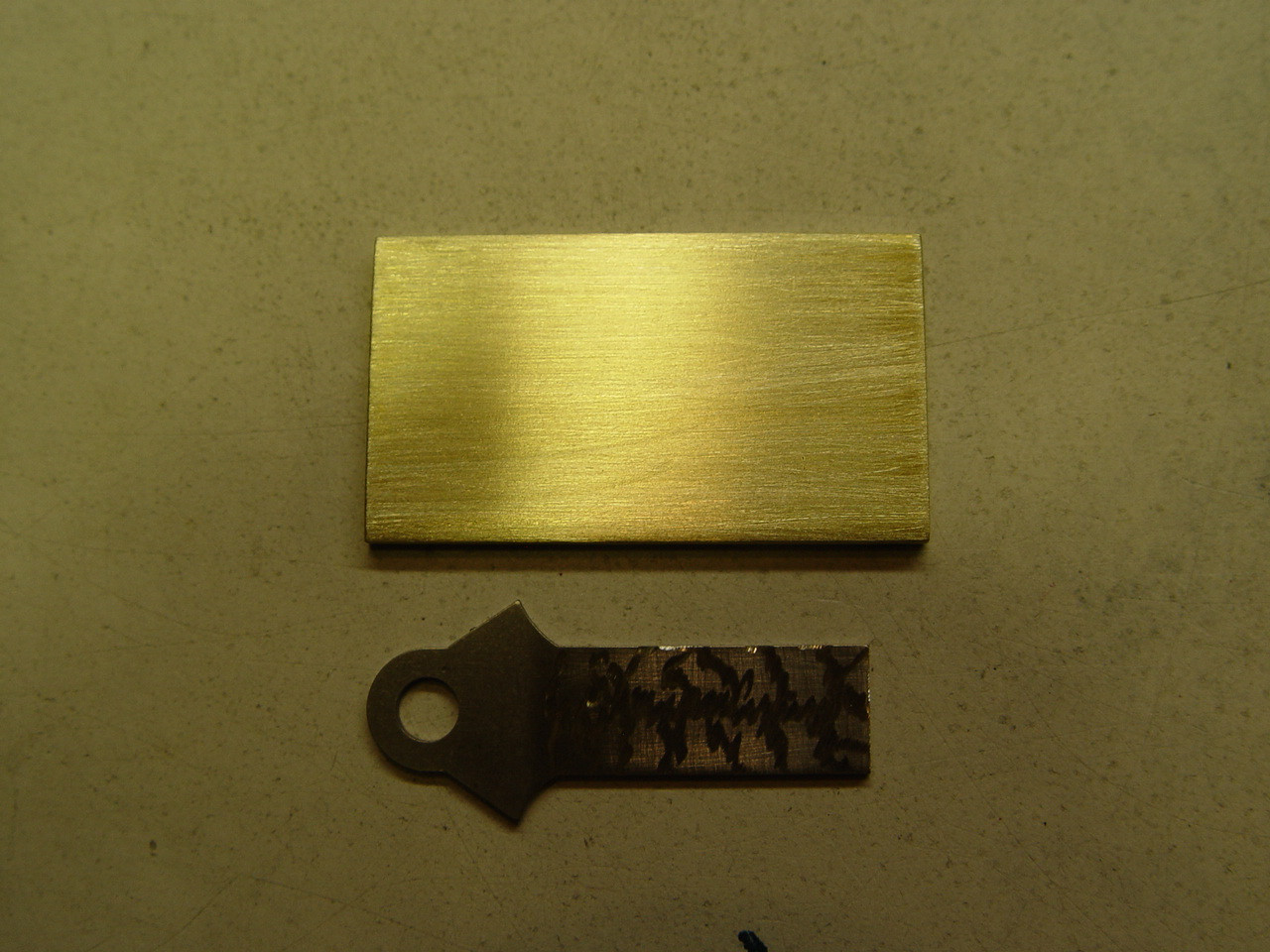
12 November 7, 2026 6:45 am
Topic: Chassis Build Measurements #1 (0 replies, posted in Dust Devil's Slot Cars)
This may take some time with all the step-by-step assembly, writing and pictures involved. If you do not know how to solder learn or have someone teach you then practice. This is NOT like soldering a wire on a motor.
Be sure to read and check everything with the pictures on each page before starting any of the chassis build steps. That way you will know what to expect
You will be able to go to any point of the build for reference. The build shown will be for a Mclaren M1 only. It is an easy build because it involves very little cutting and measuring of the brass parts.
This build will be the same soldering style for all 1/24 scale chassis. (The end outcome will be the size of the chassis to fit the body). Clubman to a NASCAR, the different measurements (length - width) and your choice of a center section and motor bracket, 1" or a 3/4-inch center section and the 1" or 3/4" for the motor bracket. That will be the differences for all different body sizes. This is just one style of many different brass chassis that can be made. Imagination and working things out are all up to you.
Measure all measurements very carefully and Sand ALL brass parts thoroughly, if you do not do this the chassis solder points Will fail and to make matters worse it will probably happen during a race.
#1 Measure the inside of the body side to side. The measurement came to 69mm. #2 I take some old brass to see what it takes to measure up to that width. For this body it will take a one 1" wide flat brass center section, two lengths of 3/32" wide brass tubes and two 3/4" wide brass flat for the side pans. With all the brass together equals 68mm. This means when the chassis is finished, the body will not have to stretch to fit the chassis. You can now put the body over the brass to see if this is acceptable where you want the body measurements to be about 1mm short of being tight against the brass. This will all play out at the end of the chassis build.
On other builds, if body folds the brass you will have to sand the outside edges of both of the 3/4" flat brass equally until you achieve a negative 1mm fit to the body. Never shave the 1" center section.
#3 Measure the body wheel wells at the top center of each well and this measurement is what you will have to work with as far as the length of the chassis.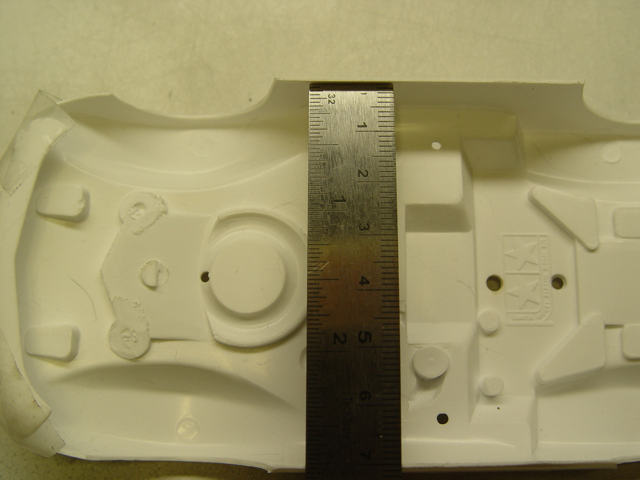
13 November 5, 2026 7:32 am
Topic: Chassis build part #3 (0 replies, posted in Dust Devil's Slot Cars)
Part #3
Before starting this section and all the rest of the build, read the page first before going on so you will know what to expect...
There are two things to remember, Clean and sand all the parts thoroughly everywhere getting all the oxidation / oils along with the excess end cut metal off each part and be very sure all the parts are as square & equal (length & width) (flat & not twisted) as possible, before soldering anything. The pictures used are a visual aid only and NOT used for any measurements.
#1 Now Sand all the brass parts top, bottom, sides, outside & ends of the tube, motor bracket and anywhere you are going to touch the brass with solder. Do not sand the front of the motor bracket. Do NOT solder anything, I will let you know when to solder. Now check if everything is equal length and width and all the brass is flat? Be sure all the bar brass is flat, level on the jig. If anything is bent / warped / twisted, you will need to flatten it. I then mark right & left on the brass, put the flat side down rounded edge side up on the jig to be soldered. Do not solder anything.
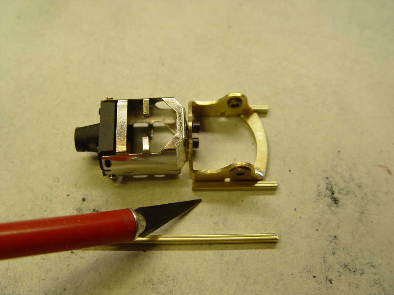
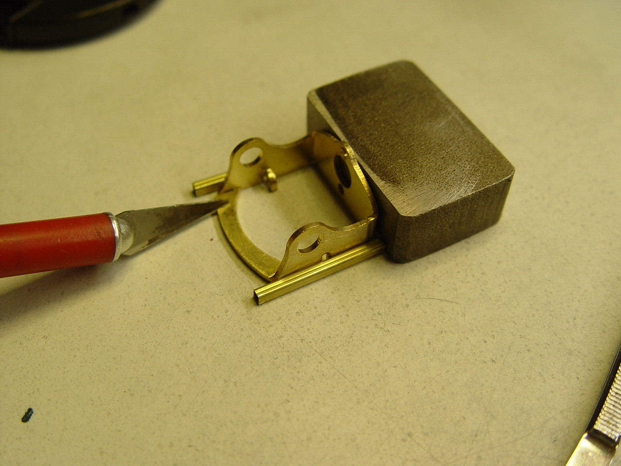
#2 Now cut two equal length 3/32" brass square tube to one inch length as shown in the picture. Sand all 4 sides of the square tube and the two sides of the motor bracket also clean out the ends of the tube so the .063 wire will slide easley through the tube. Do not sand were the motor attaches to the bracket. Remove the motor case from the housing and be sure the motor bracket is as close to perfectly square before going any farther; you will not get a second chance to do this. When this is done. #3 ( do not forget the 1/4" plate on top of the hot plate to disperse the heat evenly). Set the motor bracket on the hot plate with the two square tubes on each side of the motor bracket. Get all three brass parts on the hot plate. All parts should sit flat on the hotplate steel if you squared up all the angles of the bracket correctly, if not? square it again. #4 Then block the bracket tight with two pieces of metal or magnets as shown. Turn on the hotplate let it get HOT to operating temp. (Now this is where you test your nerves and soldering skills.) or (you can practice soldering on some old cut pieces of brass before doing the next step.) Use a bit of soldering flux on the brass before Solder the inside rear strap joint as shown at the end of the knife point (If you use this style motor bracket) then solder the outside square tube butted up tight against each side bracket you may want to use a wood secure to hold the square tube in place. Now start to solder use a little solder on the tip of the solder iron then at each end of the motor mount touch the solder to the tube & bracket, do not bump anything out of alinement or you will get to do this step again. Solder both sides. Now check to see if everything is square then finish soldering the tube to the motor mount. The bracket should look like picture #5. The two square 1" tubes should now be soldered tight against the motor bracket. If not, you get to clean up the solder mess and square it up again. Remember go slow and steady, there is no hurry. Solder everything slowly and correctly; this is NOT a race, or you will get to waste your time doing it again & again until you get it right. DO not leave the hot plate or solder iron on after each step. When you are done soldering turn everything off. Clean the parts with lighter fluid and a piece of tissue /paper towel removing all the solder flux from the brass Now you are ready to move on to the next step.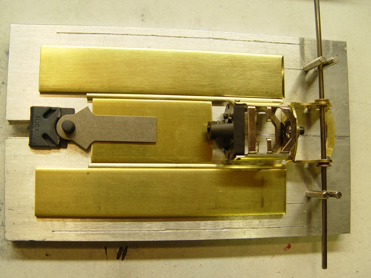
14 November 1, 2026 11:30 pm
Re: Ebay Seller Challenges! (2 replies, posted in Ebay)
I have found on E-bay that you can block bidders from bidding on your items. When you block someone watch what kind of comments you get then.
I blocked one drug infested clown, because he would bid up the auctions making the bid outrages then backout of all the bids he made a day or a few hours before the end of auction. (I think he was possibly in with the second bidder to drive up the auctions so high no one would make a bid then back out letting the second bidder to win). He started to e-mail through E-bay, why his bids would not go through. I would not answer any of his e-mails, more stupid e-mails from him, at last after the fourth he gave up. This really drives them crazy. This is just another way to play with cheats and drug infested clowns. Jim
15 October 29, 2026 10:26 am
Re: Slot Car Chassis build of the month (41 replies, posted in Modifications)
Thank you, for all the positive feedback... Jim
16 October 28, 2026 3:00 pm
Re: Slot Car Chassis build of the month (41 replies, posted in Modifications)
Hello Slot Car Builders, Collectors, & Racers:
#12
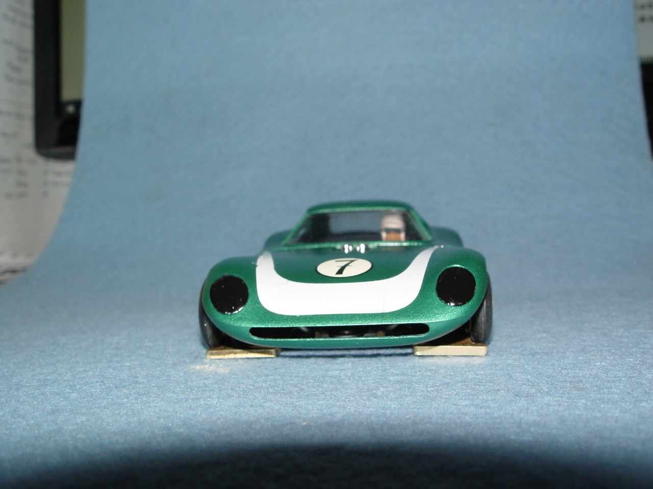
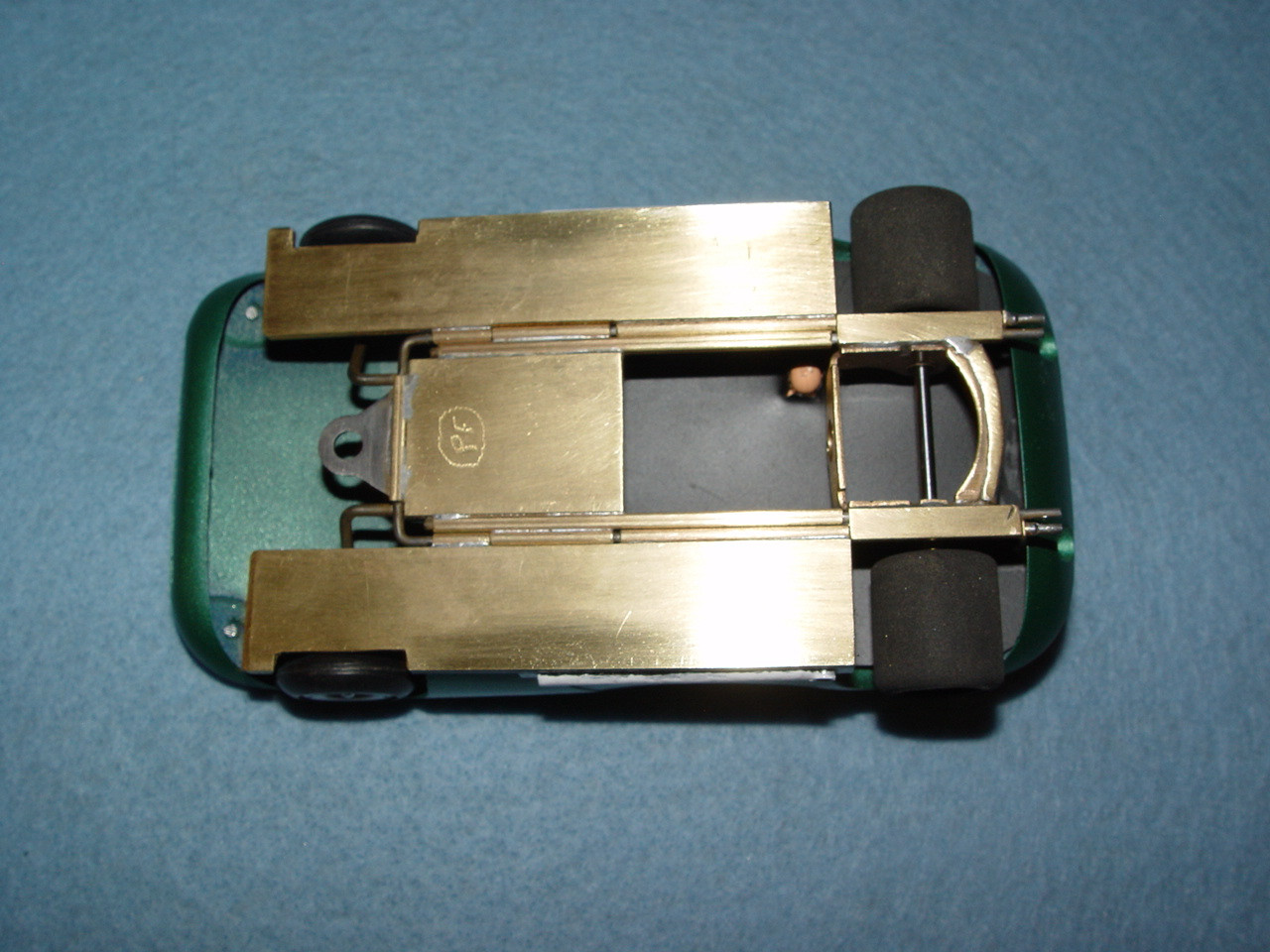
This month's build will be something most people have not seen scratch built or would not attempt to scratch build in hardbody form today. Because of the age, rarity, cost of the body or the difficulty to acquire this body makes it a very hard decision for someone to consider building. Fortunately, I had an old Cheetah body and a Russ-Kit driver lying around. They stepped up to bravely volunteer their services.
This is a collaboration between Chris aka Captain Chaos and myself.
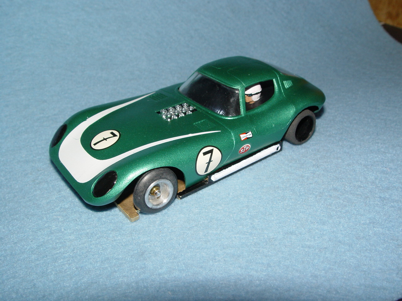
The body I started with is a Strombecker Cheetah body 1/24 scale I then built this brass chassis for the body. The wheel base is 3 9/16" It should be a handful for anyone to drive. I had to build the chassis as a large sports car then bring the dimensions down to fit the Cheetah body. I did not want to cut the body to fit the chassis. I always build the chassis to fit the body. I could not use the original side pipes because they would hang out too far from the body that would create rule problems. Here is where imagination comes in. The pictures are of how it turned out. I still need a few details to complete the chassis and body. Picture #3 Look at that happy face; he wants to go racing. (Now on to testing, adjustment Captain Chaos will be handling all those jobs). Captain Chaos has tested the Cheetah straight off the jig and it was a hand full to drive it did post a 5.67 with a so-so Super 16D motor here at Dust Devil Slot Cars racetrack. It will now need adjusting & tweaking and a better motor to get it dialed in correctly. When the testing is finished, the Cheetah will compete in Vintage USRRC and Sports Car Races. All the pictures were taken on an uneven felt surface, so the car sits wrong on the felt.
If you have any questions or need more pictures, let me know. Jim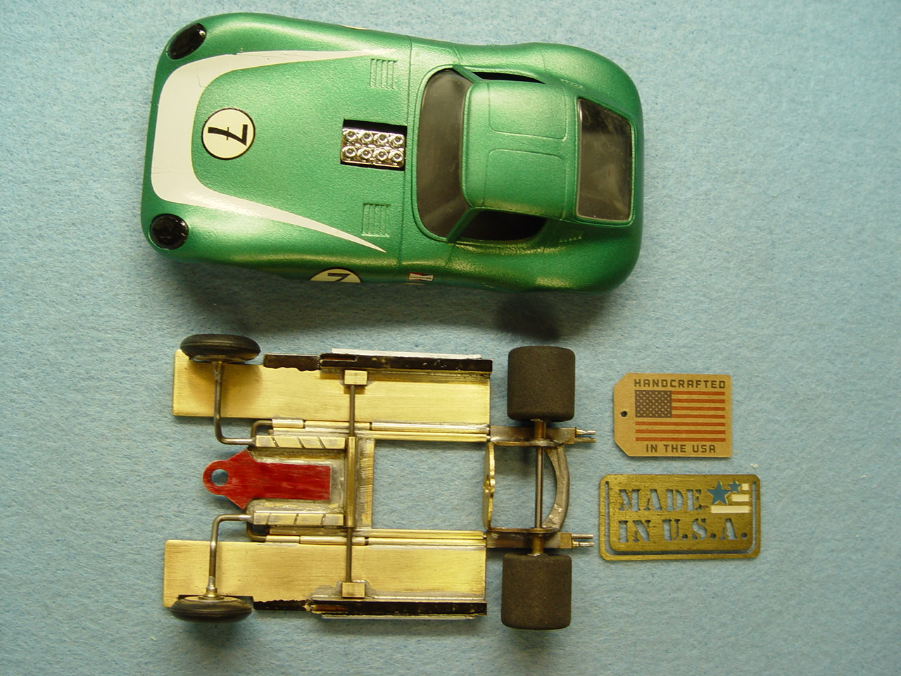
17 October 28, 2026 11:29 am
Topic: How To Build A Chassis In Pictures part #2 (0 replies, posted in Dust Devil's Slot Cars)
How To Build A Chassis In Pictures part #2
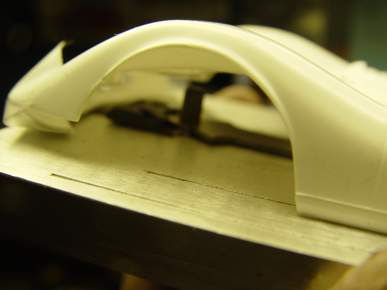
#1 Place the body on the jig and measure center to center of the wheel wells. Place your motor bracket on jig with an axle & bearings, so the axle measures up with the top of the rear wheel wells. #2 Measure the distance from the rear of the valance of the car to the guide flag, you should have 5mm - 7mm distance. Place the guide flag on the build jig along with the body to check clearance. This is the total distance you will have to work with. #3 The 1" .090 thick center section measured at 48mm long, place this under the endbell nose at the fat round circle as pictured. There are no brush housings to get in the way & no magnets in my motor housing to stick to anything. This will be your center of the chassis. Do not solder anything yet... #4 The brass you will need to cut is .090" thick 3/4" right at 104mm long measure from the front of the wheel well to the rear edge of the lower front of the body valance. This is for the side panels (bat wings). #5 cut two pieces of 3/32" round tube equal length at 78mm. From the front of the motor mount to the front edge of the 1" brass center section. The guide tongue will kind-of keep the guide flag in position. Do NOT solder anything... I will let you know when to solder. Jim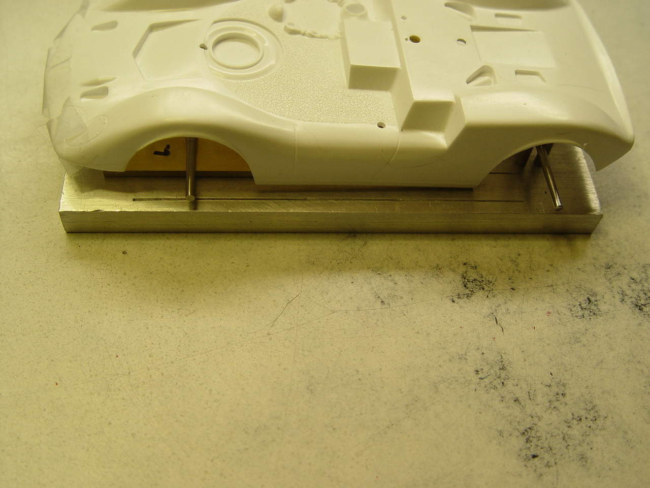
18 October 28, 2026 11:10 am
Re: Tools for Brass hardbody chassis build (2 replies, posted in Dust Devil's Slot Cars)
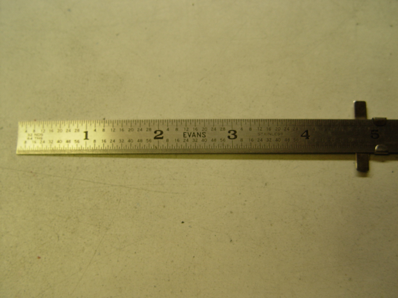
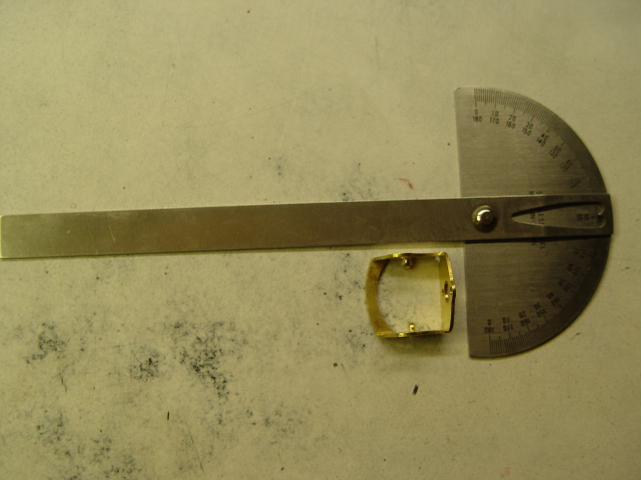
I use only Kester solder. It is available on Amazon or I sell it here. The solder is NOT cheap. Only buy what is shown on the label. There are many different solders sold by Kester. Be sure you buy this one and not some off brand that is cheaper. Notice the diameter of the solder it is .031" . Also a picture of the ruler I use not pictured in tools. I forgot a picture of a 90-degree angle to help square up the motor bracket. I found this at Hobby Lobby a few years ago. Jim 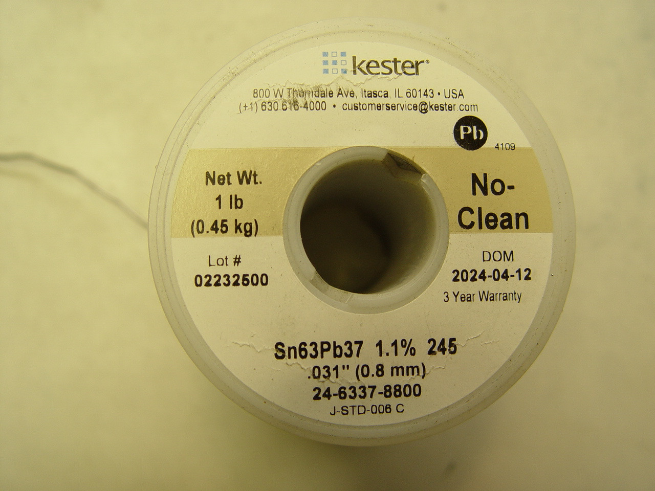
19 October 27, 2026 6:19 pm
Topic: Tools for Brass hardbody chassis build (2 replies, posted in Dust Devil's Slot Cars)
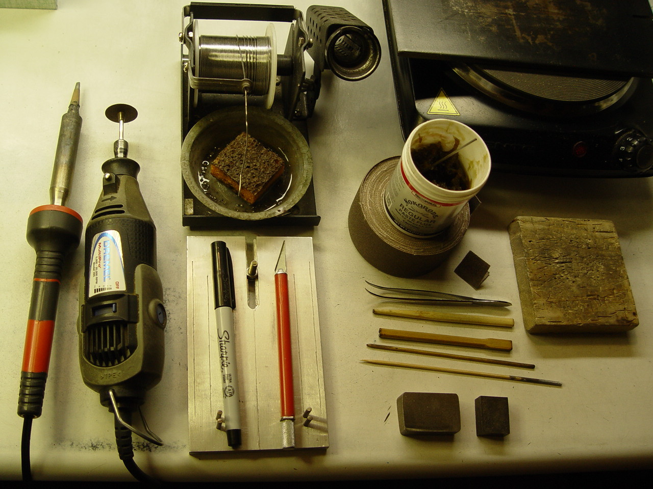
These are the tools you will need to scratch build a brass chassis.
1- A good flat surface hot plate (NOT a coil plate) a coil hot plate is a really BAD idea...
2-A flat ¼" thick steel plate 9" x 5" shown is what I use to be placed on top of the hot plate to disperse the heat evenly.
Picture #2 left to right 1–80-watt Weller solder iron, with a Weller Screwdriver tip #CT6C8 found on Amazon, a high-speed motor tool Dremel, a solder station with solder and cup with sponge, a good metal - steel or Aluminum jig ONLY to place on the hot plate -DO NOT use plastic, Corin, Phenolic or hi-temp insulated material they will all MELT. Choose wisely... A Sharpie marker, a sharp X-acto knife, a roll of emery sanding cloth it lasts longer and is easier to use than sandpaper Harbor Fright, No-clean solder Flux if you can find some, a good set of tweezers, (DO NOT use tweezers or pliers when soldering). Chop Stix and cooking skewers heat resistant Bamboo cut to size from Panda express, one or two square magnets a block of brass, steel or stainless steel, a good 6-inch ruler with millimeter or 1/64" spacing and a wood block to sand on. The steel plate positioned on the hot plate. If you use what I use the temperature setting is set at one, (if not you will have to find your own temperature setting, if you get it too hot the solder will not cool properly and possibly melt the solder joins you have already soldered, you are on your own on this one) if you use something different and it works for you keep using it. These are the tools I use that work for me. You never have enough tools, and you will find/want more as time goes on.
Here at Dust Devil Slot Cars, we sell everything needed to build anything I have posted in all the posts on this forum past or in the future. (Material, parts & tools). I do not know how to do a You Tube video.
If you have any questions or need more pictures, let me know. I cannot teach you how to solder over the phone. I will teach anyone who comes out to the shop how to do any of the steps written or pictured. Jim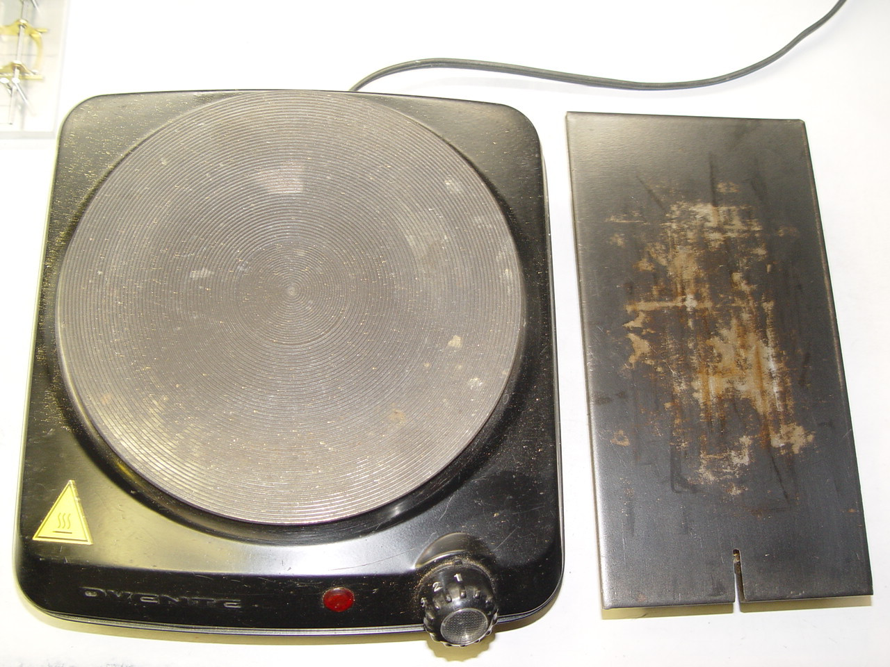
20 October 24, 2026 9:57 pm
Topic: Open Track Days #2 (0 replies, posted in Dust Devil's Slot Cars)
Dust Devil Slot Cars will have open track days for testing & tuning. Starts Oct. 24, 2026 - 12PM - 9PM Saturday & Sunday and runs until Feb. 07, 2027. Come out and see the all-new slot car shop. Racing, Parts, sales, Service, vintage, retro & modern slot cars. How to build a slot car chassis, how to set up a slot car chassis, how to build a 16D / C- can motor. Become competitive at slot car racing. The shop is eleven miles East of Redmond, Oregon Call or text for directions. If you have not been here before. Jim


21 October 7, 2026 2:48 am
Re: Open Track Days (2 replies, posted in Dust Devil's Slot Cars)
Hello Racers,
I would like to thank everyone who came out for the open track days at Dust Devil Slot Cars.
22 September 30, 2026 3:44 pm
Topic: USRRC Can-Am Racing Under OSCAR Rules (0 replies, posted in Dust Devil's Slot Cars)
This is a list of eligible Can-Am / USRRC plastic or resin hardbodies that are available. If you know of a Can-Am or USRRC plastic or resin hardbody that is not on the list that was made or is currently available, let me know and I will add it to the list. A lot of these bodies we sell at Dust Devil Slot Cars Call or text for availably or you can try e-bay, Hobby Lobby, or your local or online hobby shop.
Aston Martin-- DBR1
Chaparral-- 1, 2A, 2C, 2D, 2E, 2G, 2J
Chevrolet-- Cheetah, Grand Sport, Grand Sport Roadster, Scarab Mk1, Scarab Mk4, March 707
Dodge-- Hussein ll
Ferrari-- 206SP Spyder, 206 SP Coupe, 250 California, 250 GTO, 250 GTO SWB, 250LM, 250 Testarossa, 275P, 275LM, 330 TRI, 330P2, 330 P4, 350 Can/Am, 365P2, 860 Monza,
Ford-- J Car, GT Roadster long nose, GT Roadster, GT MKII, Honker II
Jaguar-- D,
Lister-- Jaguar, Coston
Lola-- T70
Lotus-- 23, 30, 40
Maserati-- 450S
McLaren-- Elva M1, M1B, M8
Oldsmobile-- Zerex Cooper
Porsche-- RS-60, 904 GT, 906, Carrera 910, 917
Shelby-- Cobra 289 Roadster, Cobra Daytona Coupe, Cooper King Cobra, GT40 MKII, 1967 King Cobra
Late this year or next year, we will be starting a USRRC / Can-Am Race as soon as we get twelve racers interested in participating in this event. We have new scratch built brass chassis for many of the bodies listed above. We can custom build a chassis for a body of your choice or that you may already have.
I am currently only building Can-Am, USRRC, Le Mans & Sports Cars class chassis under OSCAR rules for the next few more years. Note some chassis will be a different design depending on body length and width.
If you have questions or need more pictures, please let me know.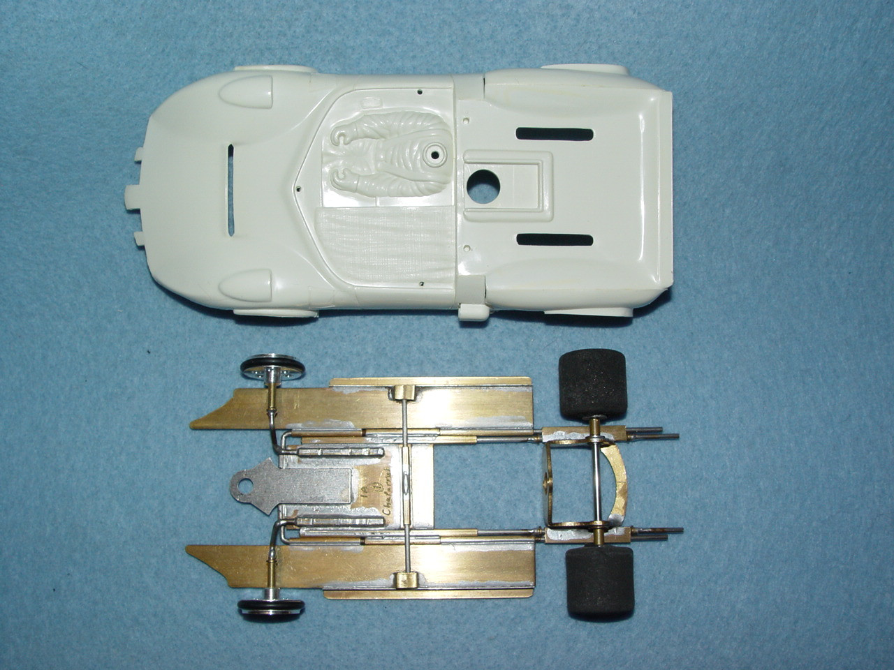

23 September 28, 2026 11:08 am
Re: OSCAR Chassis Build (2 replies, posted in Modifications)
Mike, that is a very nice build. I want to see more builds.
24 September 28, 2026 3:33 am
Re: Braid Depth (1 replies, posted in Tom's World)
The depth of Tom's track braid is basically flat with the track surface. The bottom of the guide braid shoulder should be adjusted flat to the bottom of the chassis (see picture). The thickness of the guide braid should rase the front tires off the surface of the track about .010 - .015 giving the front tires free-wheeling effect on the flat straights (also on the tech block) and the car will lean in the corners enough for the front wheels traction to be effective. 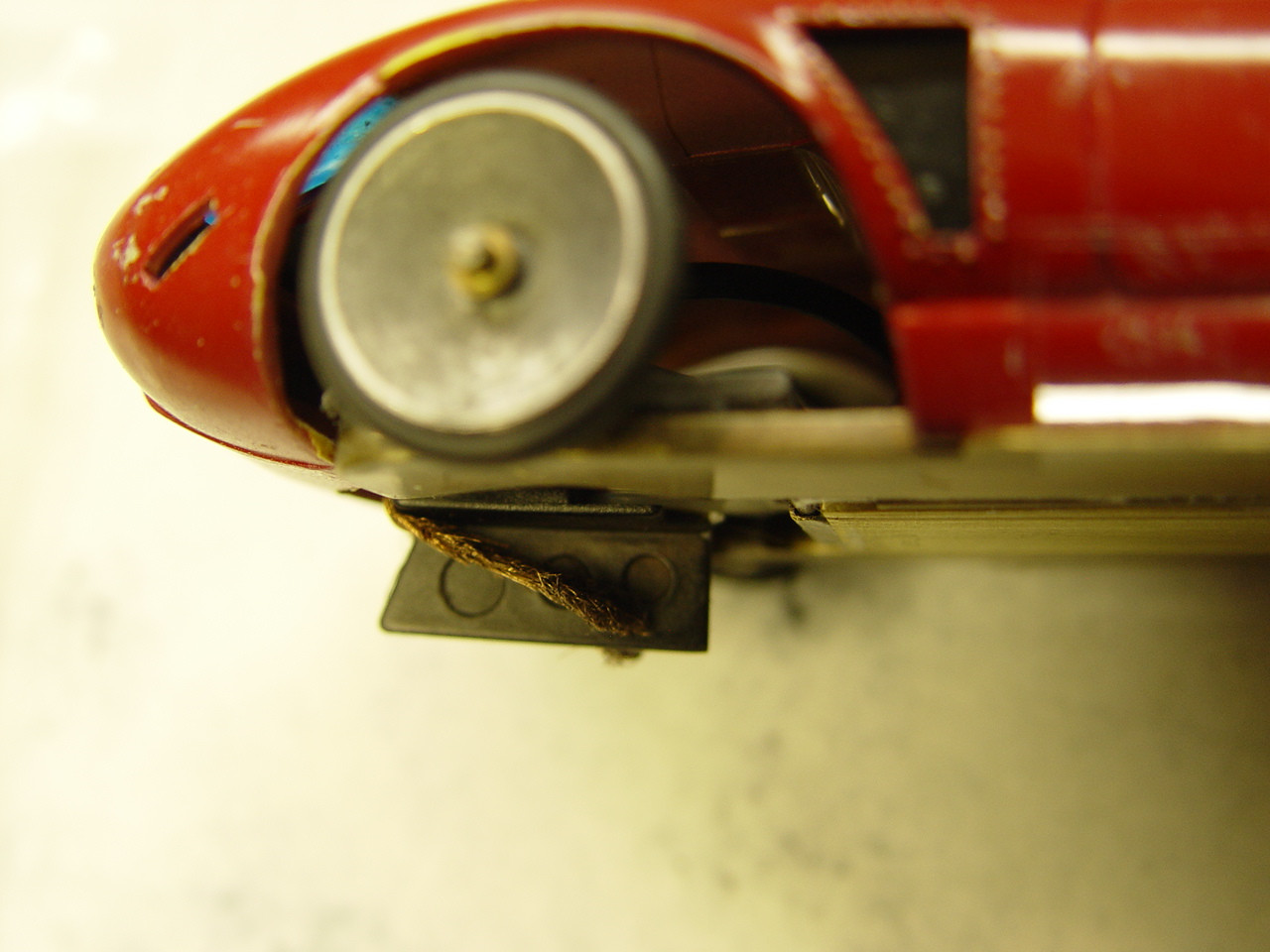
25 September 25, 2026 6:41 am
Re: Slot Car Chassis build of the month (41 replies, posted in Modifications)
Slot Car Chassis build of the month
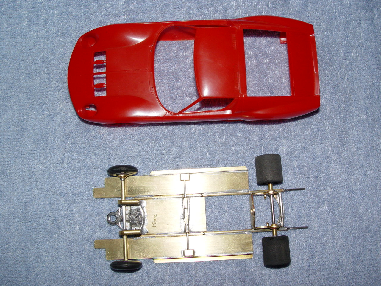
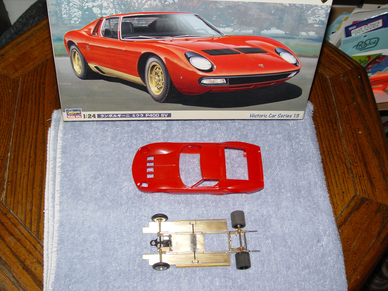
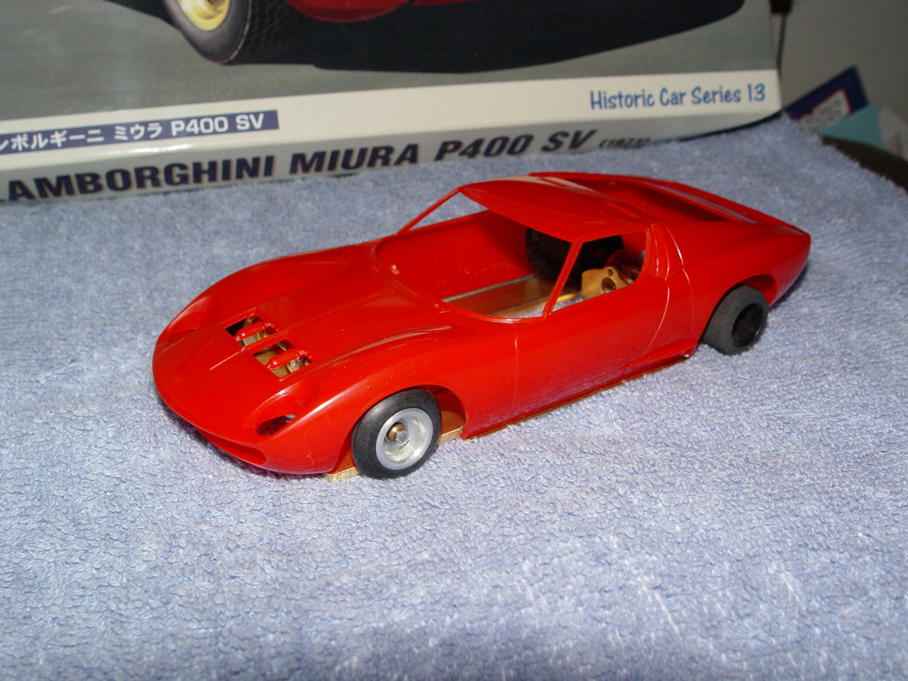
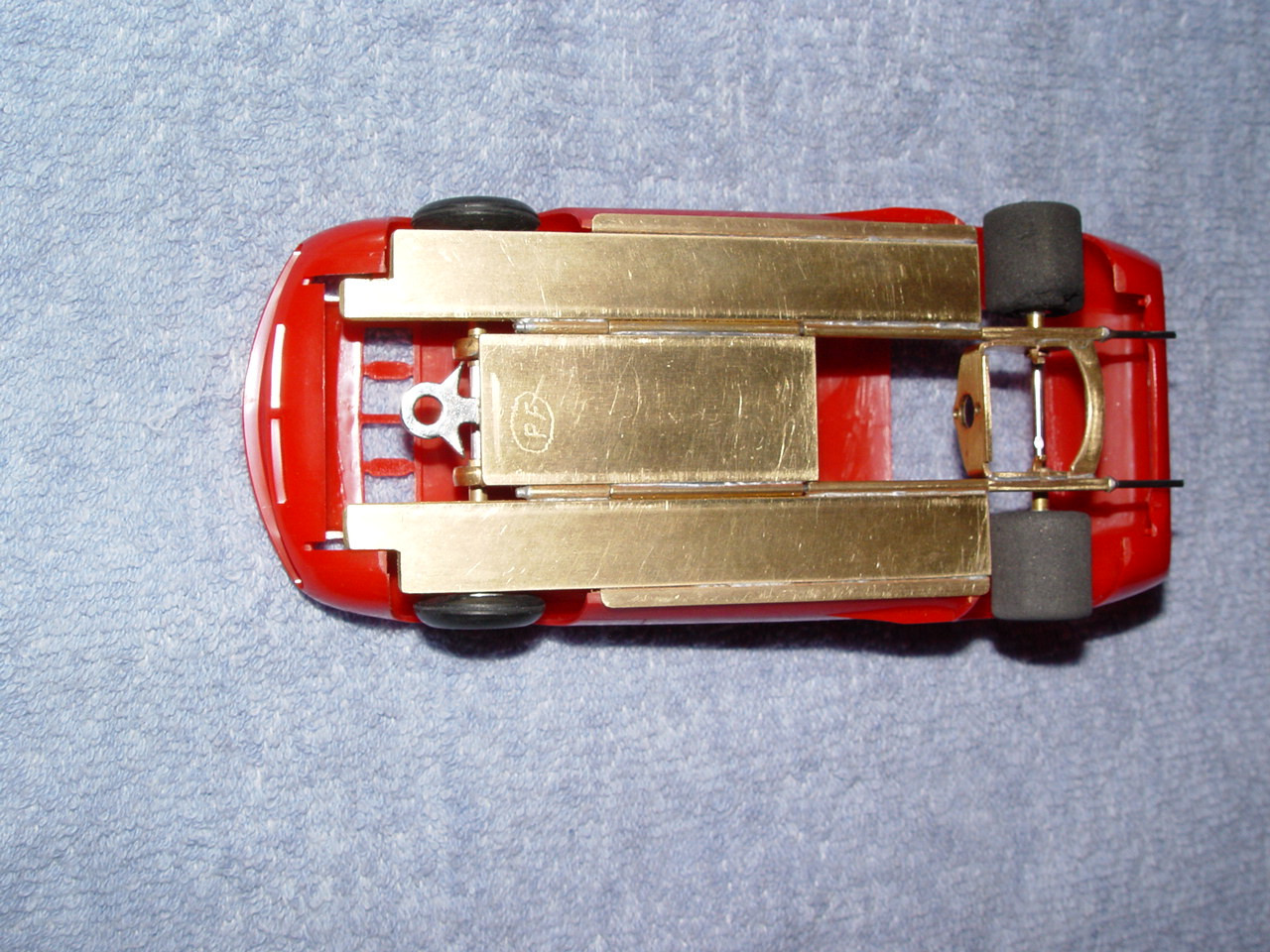
# 11
The chassis that I have just finished building last Wednesday, is for this 1971 Lamborghini Miura P400 body made by Hasegawa model kit. I have tried something different with the front axle configuration to see if the idea will work. I am always trying new ideas to see if they work out. I have also started to reinforce the rear motor / axle bracket to give the bracket more strength. I will start testing the car next week, and then I will update in this writing for the Miura.
If you have any questions or want to see more pictures, let me know and I will do my best to answer them. Jim