The previous posts to this topic were copied over from the Northwest True Scale Racers site with Howie's permission. The NTSR site is scheduled to close down at the end of this year. I will be copying over as much of the great information posted there as possible in the next few months. =====Bill
3,077 January 10, 2017 7:16 am
Re: NASTE at Rapid May. 3, 2014 (2 replies, posted in Rapid Raceway)
by wb0s » Sun May 04, 2014 7:00 pm
Thanks for hosting our race Howie! We always have a great time at Rapid Raceway! ---------------Bil
3,078 January 10, 2017 7:11 am
Topic: NASTE at Rapid May. 3, 2014 (2 replies, posted in Rapid Raceway)
by howie » Sun May 04, 2014 8:05 am
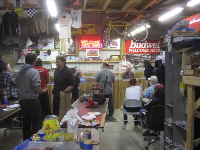
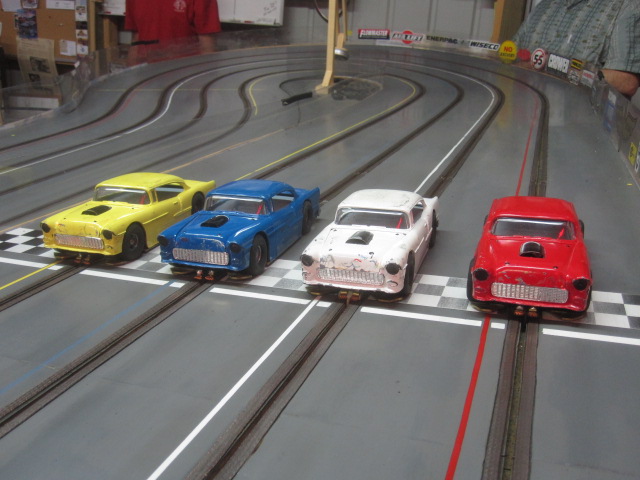
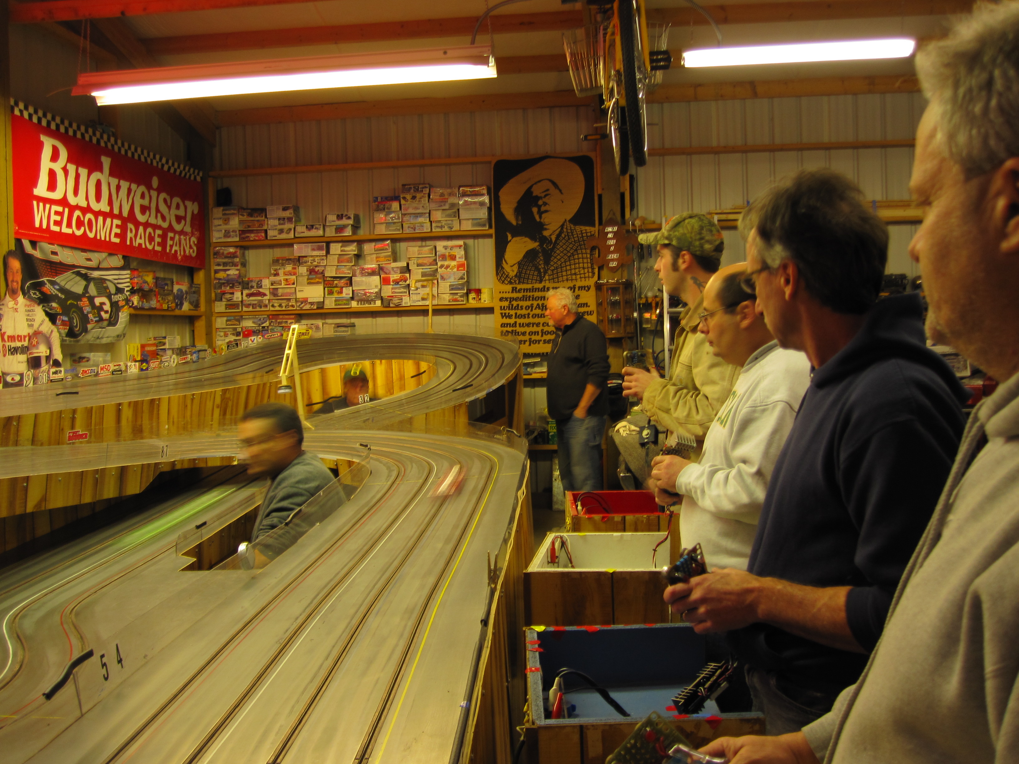
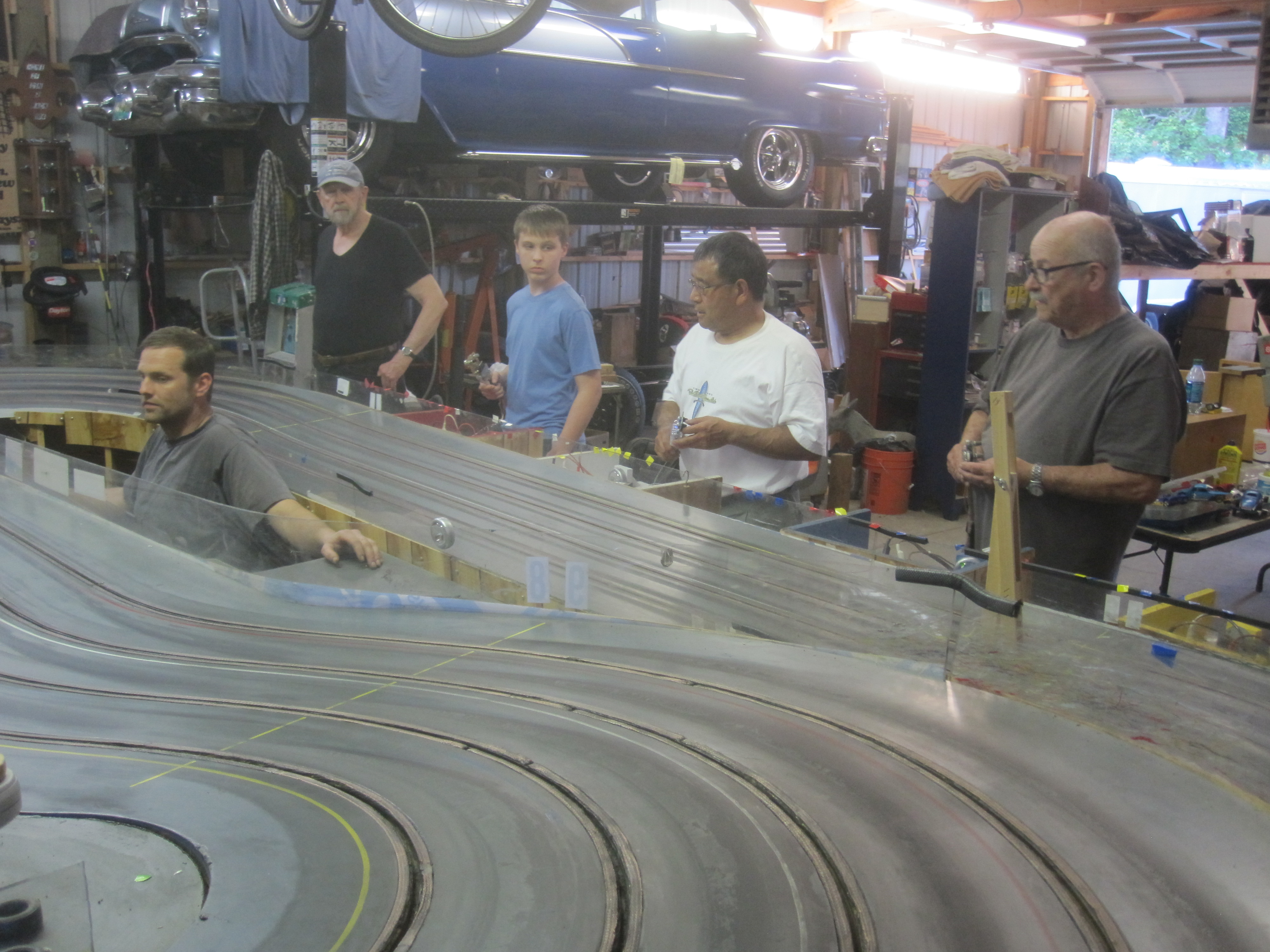
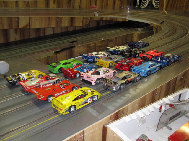
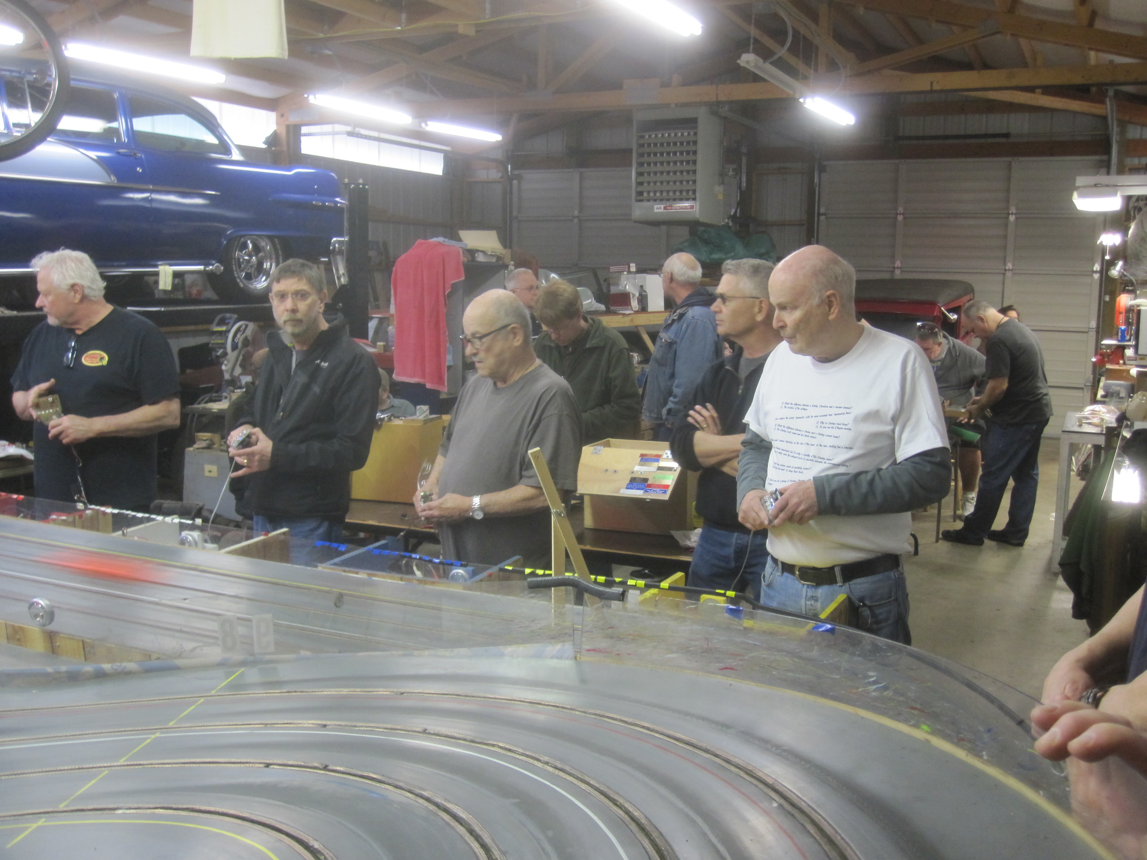
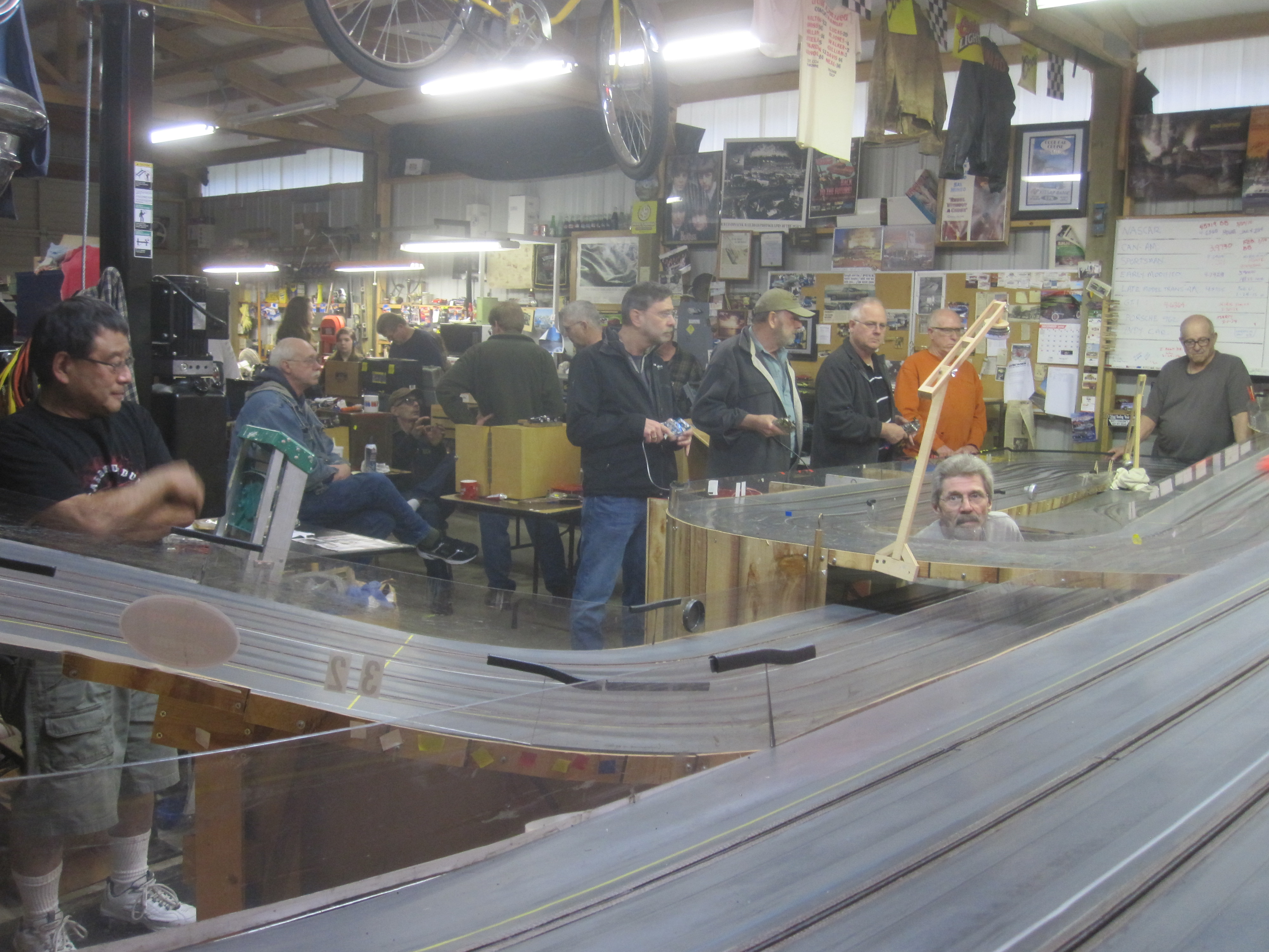
Final race at Rapid for the 2014 season and what a night it was. 20 racers showed up to do battle and eat some fine food! I don't have the final results, but Dave Smith led the way around the track in the expert division and Dorothy the "Hammer" led the way in the amateur division. It was a lot of fun as usual when the NASTE comes to race here!
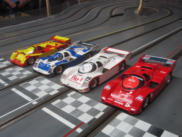
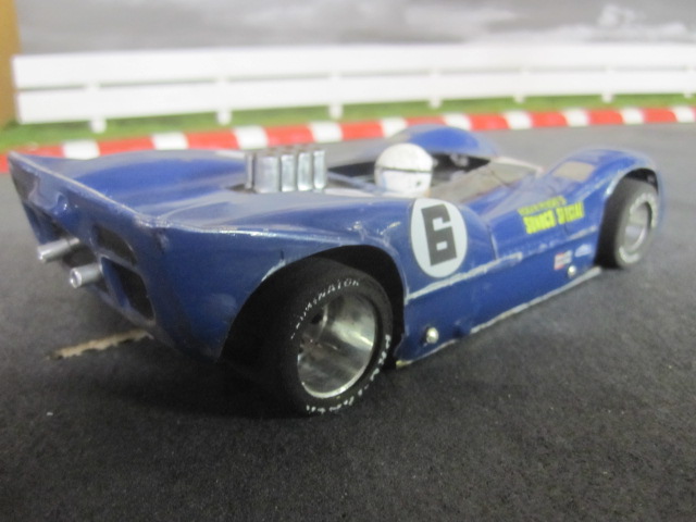
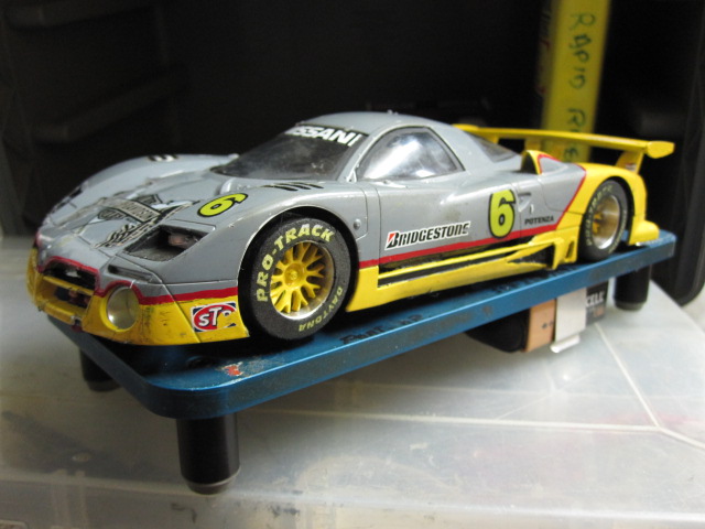
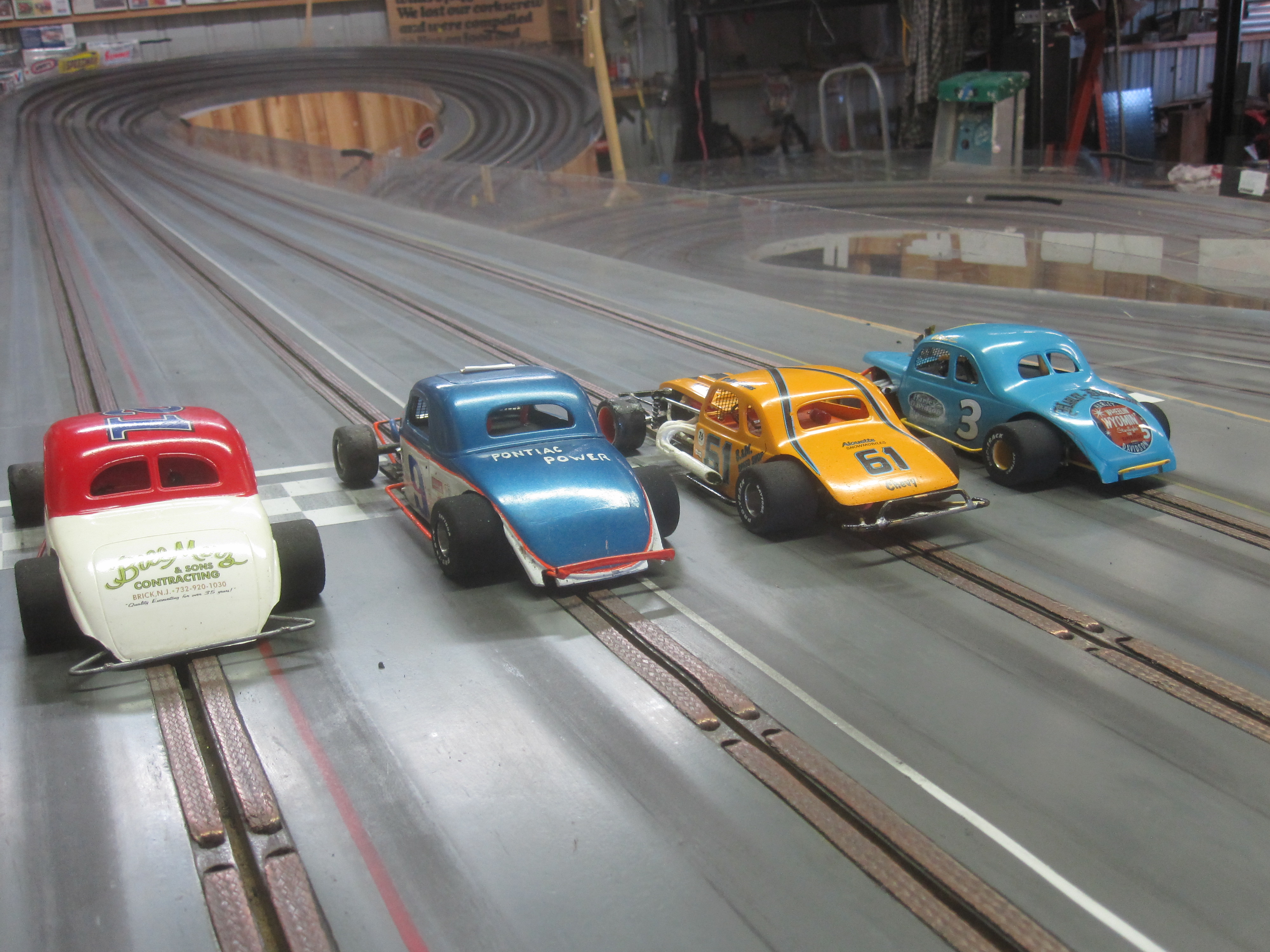
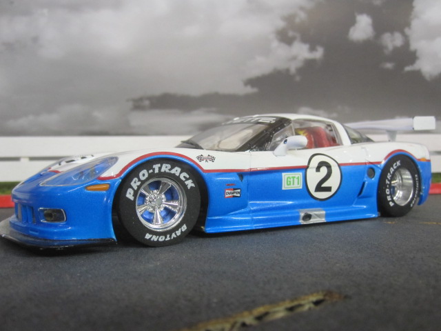
The '55 Chevy's made another appearance and new this yr. was Chris's BRM 962's, very nicely done cars.
For a more detailed race results go to the NASTE site listed in our links.
Thanks to Bill for helping clean the track and finding some braid that had come up, in fact quite a bit of it!!
Have a great summer!!
Under the bridge!
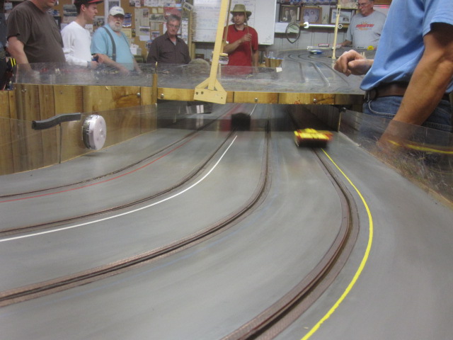
In the bank looking through the guard rail.
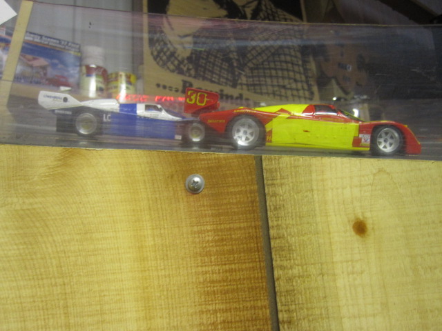
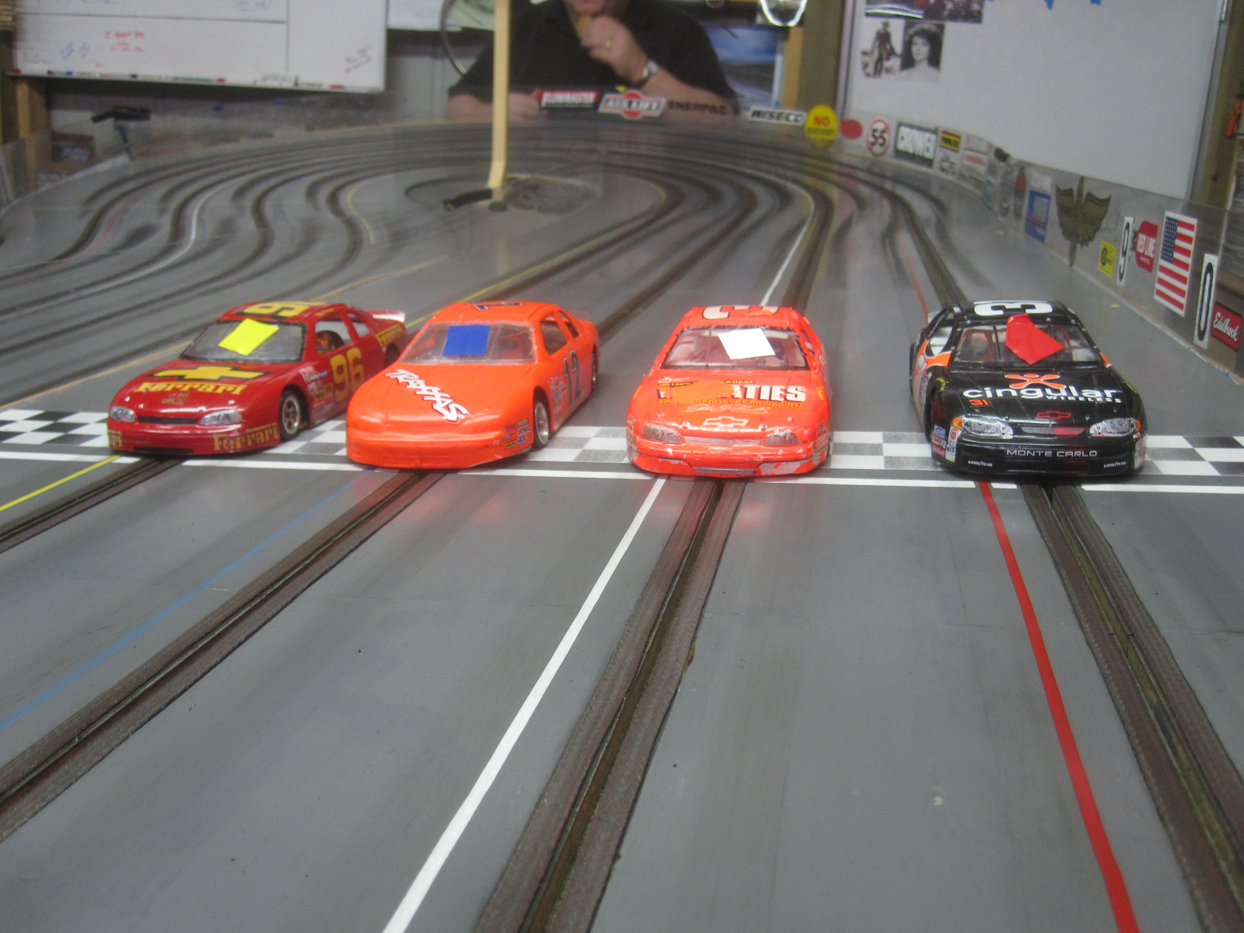
BRM 962's ready for take off!!
The always entertaining Chevy's!
3,079 January 10, 2017 7:08 am
Re: super 16D motors (2 replies, posted in Rapid Raceway)
The previous posts to this topic were copied over from the Northwest True Scale Racers site with Howie's permission. The NTSR site is scheduled to close down at the end of this year. I will be copying over as much of the great information posted there as possible in the next few months. =====Bill
3,080 January 10, 2017 7:08 am
Re: super 16D motors (2 replies, posted in Rapid Raceway)
y howie » Sun Sep 07, 2014 8:04 pm
Bob; set one up in a car, let's see how it runs. If it is equal to a Deathstar, it will be a hard sell, few racers in our area like them. Frankly, I like the path we have been taking, one motor to choose from and cheap at that!. I have several seasons on most of my Parma motors.
3,081 January 10, 2017 7:07 am
Topic: super 16D motors (2 replies, posted in Rapid Raceway)
by racerbob9 » Fri Sep 05, 2014 9:49 pm
I want to throw this out there for consideration. At the Doubleheader at Spare Time Raceway, We were given the option of running a Kelly or Proslot sealed 16D motor. The performance was about the same as a Deathstar, but they had Gold dust brushes, Better springs and the end play was consistent. The arms are balanced Chinese arms. These motors cost almost the same as a Deathstar. These motors are also available as sealed Super 16Ds. and retail for about 15 dollars at PCH parts express. I am sure we can get them cheaper through the club. This could be a cost cutting measure if they run even longer than the Parma Supers. Just looking for some feedback on this idea.
Racerbob
3,082 January 10, 2017 7:05 am
Re: NASTE Halloween Race 10-25-'14 (2 replies, posted in Rapid Raceway)
The previous posts to this topic were copied over from the Northwest True Scale Racers site with Howie's permission. The NTSR site is scheduled to close down at the end of this year. I will be copying over as much of the great information posted there as possible in the next few months. =====Bill
3,083 January 10, 2017 7:05 am
Re: NASTE Halloween Race 10-25-'14 (2 replies, posted in Rapid Raceway)
by wb0s » Thu Oct 30, 2014 10:41 am
Thanks for opening your track to us again Howie! I know everybody had a great time racing Halloween cars at Rapid Raceway! ===========Bill
3,084 January 10, 2017 6:58 am
Topic: NASTE Halloween Race 10-25-'14 (2 replies, posted in Rapid Raceway)
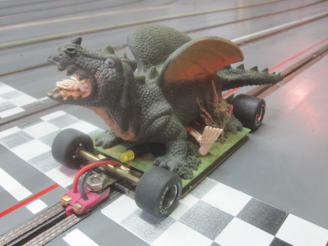
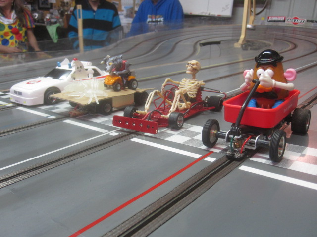
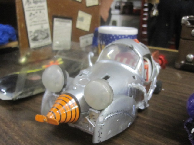
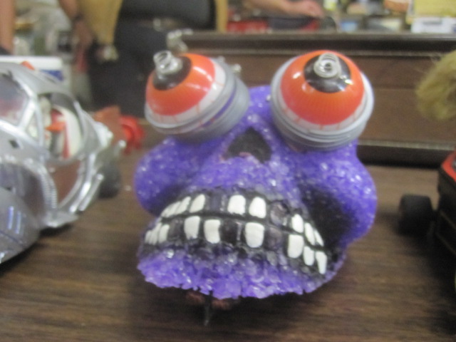
by howie » Sun Oct 26, 2014 8:57 am
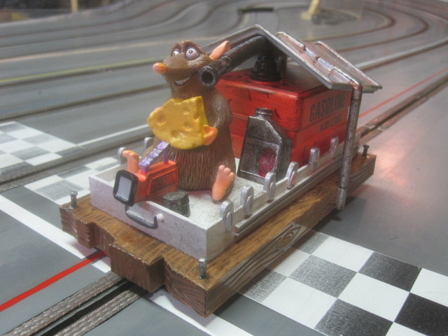
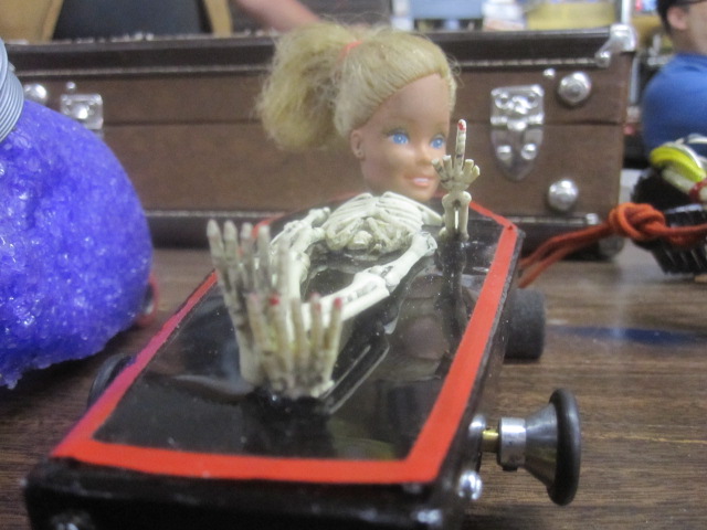
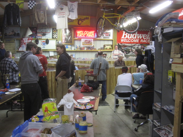
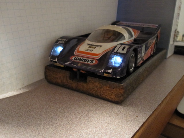
20 racers showed up with their special cars to celebrate Halloween. Plenty of good food and goodies were on hand. A lot of fun was had, made for a great and very enjoyable night. The cars were really a work of art and they really shined during the night as most had lights. There were a lot of cool cars that I missed getting pictures of.
Hammer time!!
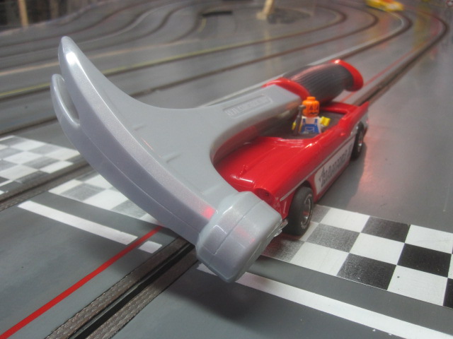
Barbie's head rotated all the way around as the car went around the track!
3,085 January 10, 2017 6:56 am
Re: Random pictures from the past (2 replies, posted in Rapid Raceway)
The previous posts to this topic were copied over from the Northwest True Scale Racers site with Howie's permission. The NTSR site is scheduled to close down at the end of this year. I will be copying over as much of the great information posted there as possible in the next few months. =====Bill
3,086 January 10, 2017 6:51 am
Re: Random pictures from the past (2 replies, posted in Rapid Raceway)
by howie » Fri Nov 07, 2014 6:04 pm
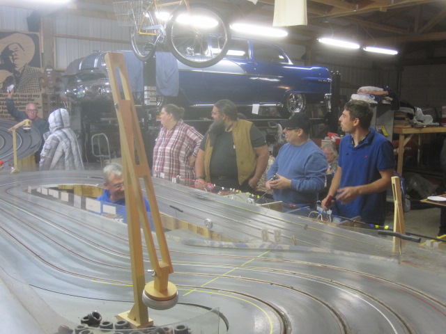
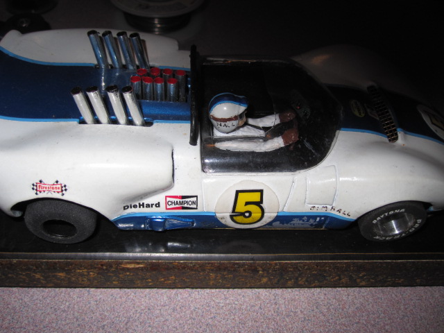
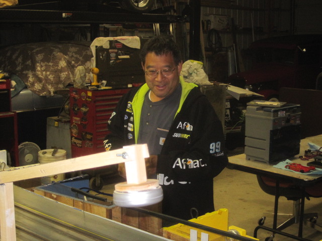
More from the past.
3,087 January 10, 2017 6:44 am
Topic: Random pictures from the past (2 replies, posted in Rapid Raceway)
by howie » Sat Nov 01, 2014 11:25 am
I came across some pictures from the past and thought I would share them. I have more and will add them to this page in time. Hope you enjoy them.
3,088 January 10, 2017 6:42 am
Re: Rapid Raceway Logo T-Shirts (1 replies, posted in Rapid Raceway)
The previous posts to this topic were copied over from the Northwest True Scale Racers site with Howie's permission. The NTSR site is scheduled to close down at the end of this year. I will be copying over as much of the great information posted there as possible in the next few months. =====Bill
3,089 January 10, 2017 6:39 am
Topic: Rapid Raceway Logo T-Shirts (1 replies, posted in Rapid Raceway)
by wb0s » Fri Dec 05, 2014 12:28 pm
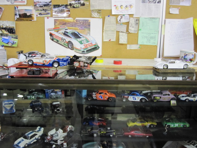
Here are the logo designs for the new Rapid Raceway T-Shirts.
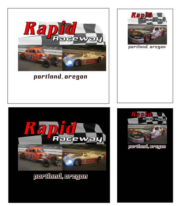
The large image of the Modifiied and the Porsche 962 will be on the backside of the shirts. The T-Shirts with just the backside image are $20.00 up to and including XL. Any size over that will be an additional $5.00.
The small image of the number 44 NASCAR is for the crest on the front side at the pocket position. The front side crest is an option for an additional $5.00.
The shirts come in black or white, same price.
If anyone would like to order a shirt directly from the manufacturer his info is listed below. He keeps the images on file.
Bob Williams.
503-260.4634.
3,090 January 10, 2017 6:37 am
Re: Race of Feb. 7th. 2015 (4 replies, posted in Rapid Raceway)
The previous posts to this topic were copied over from the Northwest True Scale Racers site with Howie's permission. The NTSR site is scheduled to close down at the end of this year. I will be copying over as much of the great information posted there as possible in the next few months. =====Bill
3,091 January 10, 2017 6:36 am
Re: Race of Feb. 7th. 2015 (4 replies, posted in Rapid Raceway)
by beaufrazier » Tue Feb 10, 2015 2:16 pm
Thanks for the great day of racing. Howie provided us all with an opportunity to get together and share some laughs. Thanks to Gary's girls for their help with lunch. Great pizza!! Thanks again Howie....
3,092 January 10, 2017 6:36 am
Re: Race of Feb. 7th. 2015 (4 replies, posted in Rapid Raceway)
by howie » Mon Feb 09, 2015 2:02 pm
It was a good day of racing Bill, thanks for sticking it out for the whole event.
There are three ladies I have to give a big THANKS to: Johneen Manno, Kala and Nia. These three cooked the four Pizzas, cut them up and delivered them to the racers. Without them, I don't know how the Pizzas would have turned out with me trying to race and oversee the racing, I probably would have burned them or worse. So a BIG thanks for the great Pizza ladies. These three may join us in racing here and they are very welcome to give it a shot and I will help as much as possible to get them on their way.
3,093 January 10, 2017 6:35 am
Re: Race of Feb. 7th. 2015 (4 replies, posted in Rapid Raceway)
by wb0s » Sun Feb 08, 2015 1:46 pm
Thanks for a great race....AND pizza Howie!!!!
3,094 January 10, 2017 6:35 am
Topic: Race of Feb. 7th. 2015 (4 replies, posted in Rapid Raceway)
by howie » Sun Feb 08, 2015 12:44 pm
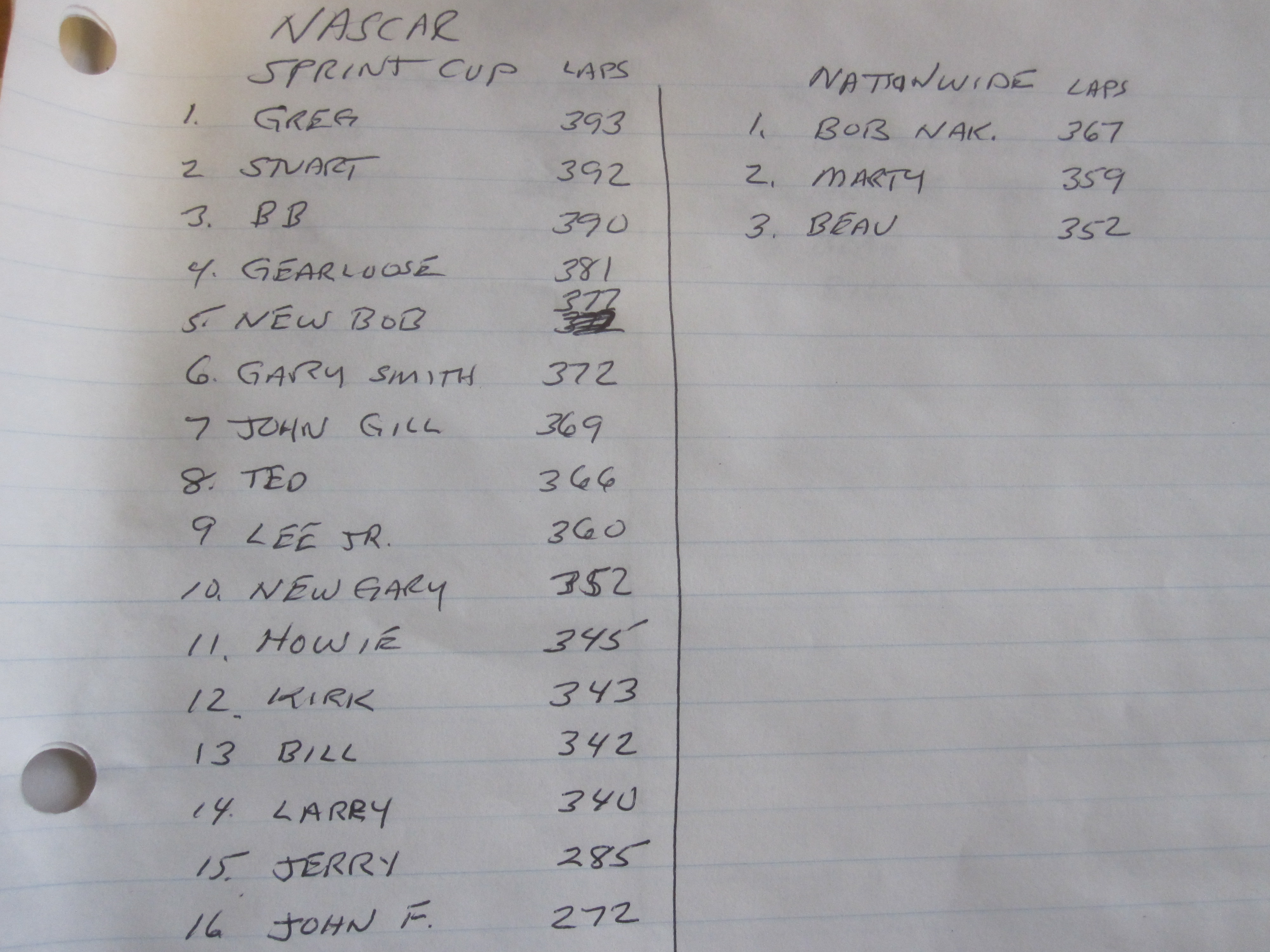
Bad Bob ( Checkered Flag ) and I decided to combine our classes for this race here at Rapid Raceway. And what a day it was. We did a NASCAR race splitting the Sprint Cup ( home builds ) and Nationwide ( Scholers ). Great turnout for the NASCAR class. Doors opened at 11:00am. and we were done with all the classes about 8:00pm. or so. A lot of racing and fun was had.
3,095 January 9, 2017 6:52 pm
Re: Northwest True Scale Racers Website (5 replies, posted in Rapid Raceway)
The previous posts to this topic were copied over from the Northwest True Scale Racers site with Howie's permission. The NTSR site is scheduled to close down at the end of this year. I will be copying over as much of the great information posted there as possible in the next few months. =====Bill
3,096 January 9, 2017 6:51 pm
Re: Northwest True Scale Racers Website (5 replies, posted in Rapid Raceway)
by wb0s » Sun Mar 29, 2015 8:28 am
I agree with Beau. I find myself coming here more often just to check for new photos. Great job Howie!!!!
3,097 January 9, 2017 6:50 pm
Re: Northwest True Scale Racers Website (5 replies, posted in Rapid Raceway)
by beaufrazier » Sat Mar 28, 2015 9:28 am
Love the changes to the home page. It does peak your interest to want to know more....Beau
3,098 January 9, 2017 6:50 pm
Re: Northwest True Scale Racers Website (5 replies, posted in Rapid Raceway)
by marty » Thu Mar 26, 2015 7:18 am
I like the new look. Good work guys.
Marty
3,099 January 9, 2017 6:50 pm
Re: Northwest True Scale Racers Website (5 replies, posted in Rapid Raceway)
by howie » Wed Mar 25, 2015 6:28 pm
Thanks to Bill for coming over here and setting this up and trying to get me up to speed on this system, while Monte was on the speaker phone with us to give us technical support. Bill was here for about 4hrs. or so. I tried to go through the steps last night and failed 'till Bill got on the web and showed me a step I was missing, so a lot of hrs. on this project. I think I got it now, maybe, well hopefully, I guess we will see! Thanks Bill and Monte.
3,100 January 9, 2017 6:50 pm
Topic: Northwest True Scale Racers Website (5 replies, posted in Rapid Raceway)
by wb0s » Wed Mar 25, 2015 3:16 pm
The website upgrades are looking good Howie! Thank you for all the effort you are puting into your site!